Toyota CH-R Service Manual: Radio Broadcast cannot be Received or Poor Reception
PROCEDURE
|
1. |
CHECK RADIO RECEIVER ASSEMBLY |
(a) Check the radio automatic station search function.
(1) Check the radio automatic station search function by activating it.
|
Result |
Proceed to |
|---|---|
|
Automatic station search function does not stop |
A |
|
Automatic station search function stops on a station |
B |
| B | .gif) |
REPLACE RADIO RECEIVER ASSEMBLY |
|
.gif)
|
2. |
CHECK OPTIONAL COMPONENTS |
(a) Check if any optional components that may decrease reception capacity, such as sunshade film, are installed.
|
Result |
Proceed to |
|---|---|
|
Optional components are installed |
A |
|
Optional components are not installed |
B |
NOTICE:
Do not remove optional components without the permission of the customer.
| A | |
REMOVE OPTIONAL COMPONENTS AND CHECK AGAIN (SEE NOTICE ABOVE) |
|
|
3. |
CHECK RADIO RECEIVER ASSEMBLY |
|
(a) Preparation for check (1) Disconnect the antenna connector from the radio receiver assembly. |
|
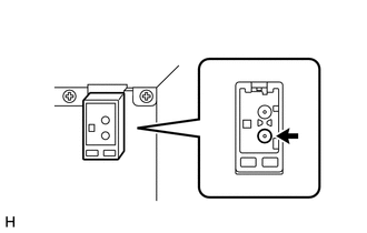
(b) Check for noise
(1) Turn the ignition switch to ACC with the radio receiver assembly connectors connected.
(2) Turn the radio receiver assembly on and enter AM mode.
(3) Place a screwdriver, thin wire or other metal object on the radio receiver assembly antenna jack and check that noise can be heard from the speakers.
OK:
Noise occurs.
| NG | |
REPLACE RADIO RECEIVER ASSEMBLY |
|
|
4. |
INSPECT RADIO RECEIVER ASSEMBLY |
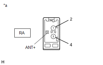
(a) Disconnect the RA radio receiver assembly connector.
|
(b) Measure the voltage according to the value(s) in the table below. Standard Voltage:
|
|
| NG | |
REPLACE RADIO RECEIVER ASSEMBLY |
|
|
5. |
REPLACE ANTENNA CORD SUB-ASSEMBLY |
(a) Replace the antenna cord sub-assembly and check if radio broadcasts can be received normally.
Click here
.gif)
OK:
Radio broadcasts can be received normally.
| OK | |
END |
|
|
6. |
REPLACE NO. 2 ANTENNA CORD SUB-ASSEMBLY |
(a) Replace the No. 2 antenna cord sub-assembly and check if radio broadcasts can be received normally.
Click here
OK:
Radio broadcasts can be received normally.
| OK | |
END |
|
|
7. |
REPLACE NO. 3 ANTENNA CORD SUB-ASSEMBLY |
(a) Replace the No. 3 antenna cord sub-assembly with a new or known good one and check if radio broadcasts can be received normally.
Click here
OK:
Radio broadcasts can be received normally.
| OK | |
END |
|
|
8. |
REPLACE ROOF ANTENNA ASSEMBLY |
(a) Replace the roof antenna assembly and check if radio broadcasts can be received normally.
Click here
OK:
Radio broadcasts can be received normally.
| OK | |
END |
| NG | |
REPLACE RADIO RECEIVER ASSEMBLY |
 CD Sound Skips
PROCEDURE
1.
CHECK CD
(a) Check that the CD is not deformed or cracked.
OK:
No deformation or cracks on the CD
...
 Panel Switches do not Function
PROCEDURE
1.
CHECK PANEL SWITCH
(a) Check for foreign matter around the switches that might prevent operation.
OK:
No foreign matter is found.
OK
...
Other materials:
Toyota CH-R Owners Manual > Do-it-yourself maintenance: Wheels
If a wheel is bent, cracked or heavily corroded, it should be replaced.
Otherwise, the tire may separate from the wheel or cause a loss of handling control.
Wheel selection
When replacing wheels, care should be taken to ensure that they are equivalent
to those removed in load capacity, diamete ...
Toyota CH-R Service Manual > Brake Master Cylinder: Removal
REMOVAL
CAUTION / NOTICE / HINT
The necessary procedures (adjustment, calibration, initialization, or registration)
that must be performed after parts are removed, installed, or replaced during the
brake master cylinder sub-assembly removal/installation are shown below.
Necessary Procedure Af ...
Toyota C-HR (AX20) 2023-2026 Owner's Manual
Toyota CH-R Owners Manual
- For safety and security
- Instrument cluster
- Operation of each component
- Driving
- Interior features
- Maintenance and care
- When trouble arises
- Vehicle specifications
- For owners
Toyota CH-R Service Manual
- Introduction
- Maintenance
- Audio / Video
- Cellular Communication
- Navigation / Multi Info Display
- Park Assist / Monitoring
- Brake (front)
- Brake (rear)
- Brake Control / Dynamic Control Systems
- Brake System (other)
- Parking Brake
- Axle And Differential
- Drive Shaft / Propeller Shaft
- K114 Cvt
- 3zr-fae Battery / Charging
- Networking
- Power Distribution
- Power Assist Systems
- Steering Column
- Steering Gear / Linkage
- Alignment / Handling Diagnosis
- Front Suspension
- Rear Suspension
- Tire / Wheel
- Tire Pressure Monitoring
- Door / Hatch
- Exterior Panels / Trim
- Horn
- Lighting (ext)
- Mirror (ext)
- Window / Glass
- Wiper / Washer
- Door Lock
- Heating / Air Conditioning
- Interior Panels / Trim
- Lighting (int)
- Meter / Gauge / Display
- Mirror (int)
- Power Outlets (int)
- Pre-collision
- Seat
- Seat Belt
- Supplemental Restraint Systems
- Theft Deterrent / Keyless Entry

0.0094