
Toyota CH-R Service Manual: Open in Outside Luggage Compartment Electrical Key Antenna Circuit (B27A8)
DESCRIPTION
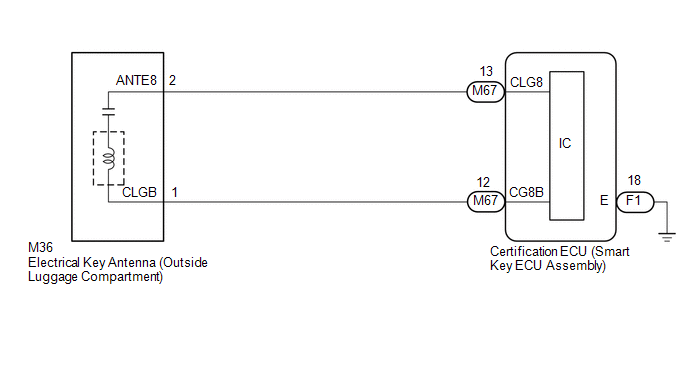
The certification ECU (smart key ECU assembly) generates a request signal and transmits the signal to the electrical key antenna (outside luggage compartment). For the electrical key antenna (outside luggage compartment) to detect when the electrical key transmitter sub-assembly is brought close to the vehicle, the received request signal is transmitted within approximately 1 m (3.28 ft.) of the back door. DTC B27A8 is stored by the certification ECU (smart key ECU assembly) when an open is detected between the certification ECU (smart key ECU assembly) and electrical key antenna (outside luggage compartment) (between terminals CLG8 and ANTE8, or terminals CG8B and CLGB).
|
DTC No. |
Detection Item |
DTC Detection Condition |
Trouble Area |
Note |
|---|---|---|---|---|
|
B27A8 |
Open in Outside Luggage Compartment Electrical Key Antenna Circuit |
An open is detected in the circuit between the certification ECU (smart key ECU assembly) and electrical key antenna (outside luggage compartment) (CLG8 - ANTE8, CG8B - CLGB) (1 trip detection logic*). |
|
|
- *: Only output while a malfunction is present and the engine switch is on (IG).
|
Vehicle Condition when Malfunction Detected |
Fail-safe Operation when Malfunction Detected |
|---|---|
|
Entry lock/unlock operation cannot be performed for back door |
- |
|
DTC No. |
Data List and Active Test |
|---|---|
|
B27A8 |
Key diagnostic mode can be used to perform troubleshooting |
WIRING DIAGRAM
CAUTION / NOTICE / HINT
NOTICE:
- The smart key system (for Entry Function) uses the LIN communication
system and CAN communication system. Inspect the communication function
by following How to Proceed with Troubleshooting. Troubleshoot the smart
key system (for Entry Function) after confirming that the communication
systems are functioning properly.
Click here
.gif)
- When using the Techstream with the engine switch off, connect the Techstream to the DLC3 and turn a courtesy light switch on and off at intervals of 1.5 seconds or less until communication between the Techstream and the vehicle begins. Then select the vehicle type under manual mode and enter the following menus: Body Electrical / Smart Key. While using the Techstream, periodically turn a courtesy light switch on and off at intervals of 1.5 seconds or less to maintain communication between the Techstream and the vehicle.
- Before replacing the certification ECU (smart key ECU assembly), refer
to Precaution.
Click here
- After repair, confirm that no DTCs are output by performing "DTC Output Confirmation Operation".
PROCEDURE
|
1. |
CHECK CONNECTOR CONNECTION |
(a) Check that the connectors are properly connected to the certification ECU (smart key ECU assembly) and electrical key antenna (outside luggage compartment).
OK:
Connectors are properly connected.
| NG | .gif) |
CONNECT CONNECTORS PROPERLY |
|
.gif)
|
2. |
CHECK HARNESS AND CONNECTOR (CERTIFICATION ECU (SMART KEY ECU ASSEMBLY) - ELECTRICAL KEY ANTENNA (OUTSIDE LUGGAGE COMPARTMENT)) |
(a) Disconnect the M67 and F1 certification ECU (smart key ECU assembly) connectors.
(b) Disconnect the M36 electrical key antenna (outside luggage compartment) connector.
(c) Measure the resistance according to the value(s) in the table below.
Standard Resistance:
|
Tester Connection |
Condition |
Specified Condition |
|---|---|---|
|
M67-13 (CLG8) - M36-2 (ANTE8) |
Always |
Below 1 Ω |
|
M67-12 (CG8B) - M36-1 (CLGB) |
Always |
Below 1 Ω |
|
F1-18 (E) - Body ground |
Always |
Below 1 Ω |
|
M67-13 (CLG8) or M36-2 (ANTE8) - Body ground |
Always |
10 kΩ or higher |
|
M67-12 (CG8B) or M36-1 (CLGB) - Body ground |
Always |
10 kΩ or higher |
(d) Reconnect the M67 and F1 certification ECU (smart key ECU assembly) connectors.
| NG | |
REPAIR OR REPLACE HARNESS OR CONNECTOR |
|
|
3. |
CHECK CERTIFICATION ECU (SMART KEY ECU ASSEMBLY) (OUTPUT TO ELECTRICAL KEY ANTENNA (OUTSIDE LUGGAGE COMPARTMENT)) |
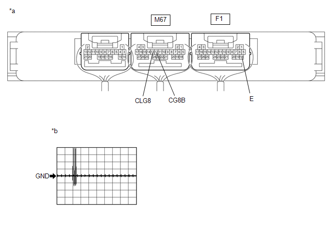
|
*a |
Component with harness connected (Certification ECU (Smart Key ECU Assembly)) |
*b |
Waveform 1 |
(a) Using an oscilloscope, check the waveform.
OK:
|
Tester Connection |
Condition |
Tool Setting |
Specified Condition |
|---|---|---|---|
|
M67-13 (CLG8) - F1-18 (E) |
Procedure:
|
2 V/DIV., 500 ms/DIV. |
Pulse generation (See waveform 1) |
|
M67-12 (CG8B) - F1-18 (E) |
Procedure:
|
2 V/DIV., 500 ms/DIV. |
Pulse generation (See waveform 1) |
| NG | |
REPLACE CERTIFICATION ECU (SMART KEY ECU ASSEMBLY) |
|
|
4. |
REPLACE ELECTRICAL KEY ANTENNA (OUTSIDE LUGGAGE COMPARTMENT) |
(a) Temporarily replace the electrical key antenna (outside luggage compartment) with a new or known good one.
Click here
|
|
5. |
CLEAR DTC |
(a) Clear the DTCs.
Body Electrical > Smart Key > Clear DTCs
|
|
6. |
CHECK FOR DTC |
(a) Check for DTCs.
Body Electrical > Smart Key > Trouble CodesOK:
DTC B27A8 is not output.
| OK | |
END (ELECTRICAL KEY ANTENNA (OUTSIDE LUGGAGE COMPARTMENT) WAS DEFECTIVE) |
| NG | |
REPLACE CERTIFICATION ECU (SMART KEY ECU ASSEMBLY) |
 Open in Front Passenger Side Electrical Antenna Circuit (B27A2)
DESCRIPTION
The certification ECU (smart key ECU assembly) generates a request signal and
transmits the signal to the front door outside handle assembly RH (electrical key
antenna) at intervals o ...
 All Door Entry Lock/Unlock Functions and Wireless Functions do not Operate
DESCRIPTION
If the entry lock and wireless door lock operations cannot be performed, the
electrical key and TPMS receiver assembly may be malfunctioning, or there may be
wave interference or prob ...
Other materials:
Toyota CH-R Owners Manual > Engine compartment: Engine oil
With the engine at operating temperature and turned off, check the oil level
on the dipstick.
■ Checking the engine oil
1. Park the vehicle on level ground. After warming up the engine and turning
it off, wait more than 5 minutes for the oil to drain back into the bottom of the
engine.
2. ...
Toyota CH-R Service Manual > Meter / Gauge System: Operating Light Control Rheostat does not Change Light Brightness
DESCRIPTION
The illumination intensity of the combination meter is increased by turning the
knob of the light control rheostat upward, and decreased by turning the knob downward.
WIRING DIAGRAM
CAUTION / NOTICE / HINT
NOTICE:
When replacing the combination meter assembly, always replace it ...
Toyota C-HR (AX20) 2023-2026 Owner's Manual
Toyota CH-R Owners Manual
- For safety and security
- Instrument cluster
- Operation of each component
- Driving
- Interior features
- Maintenance and care
- When trouble arises
- Vehicle specifications
- For owners
Toyota CH-R Service Manual
- Introduction
- Maintenance
- Audio / Video
- Cellular Communication
- Navigation / Multi Info Display
- Park Assist / Monitoring
- Brake (front)
- Brake (rear)
- Brake Control / Dynamic Control Systems
- Brake System (other)
- Parking Brake
- Axle And Differential
- Drive Shaft / Propeller Shaft
- K114 Cvt
- 3zr-fae Battery / Charging
- Networking
- Power Distribution
- Power Assist Systems
- Steering Column
- Steering Gear / Linkage
- Alignment / Handling Diagnosis
- Front Suspension
- Rear Suspension
- Tire / Wheel
- Tire Pressure Monitoring
- Door / Hatch
- Exterior Panels / Trim
- Horn
- Lighting (ext)
- Mirror (ext)
- Window / Glass
- Wiper / Washer
- Door Lock
- Heating / Air Conditioning
- Interior Panels / Trim
- Lighting (int)
- Meter / Gauge / Display
- Mirror (int)
- Power Outlets (int)
- Pre-collision
- Seat
- Seat Belt
- Supplemental Restraint Systems
- Theft Deterrent / Keyless Entry

0.0087