Toyota CH-R Service Manual: Installation
INSTALLATION
PROCEDURE
1. INSTALL LOWER NO. 1 INSTRUMENT PANEL AIRBAG DOOR (for TMMT Made)
|
(a) Engage the hooks. |
|
.png)
|
(b) Engage the hooks to install the lower No. 1 instrument panel airbag door to the lower No. 1 instrument panel airbag assembly. |
|
.png)
2. INSTALL LOWER NO. 1 INSTRUMENT PANEL AIRBAG ASSEMBLY WITH DOOR
(a) Check that the ignition switch off.
(b) Check that the cable is disconnected from the negative (-) battery terminal.
CAUTION:
Wait at least 90 seconds after disconnecting the cable from the negative (-) battery terminal to disable the SRS system.
.png)
|
(c) Connect the airbag connector to the lower No. 1 instrument panel airbag assembly with door. NOTICE: When connecting any airbag connector, take care not to damage the airbag wire harness. |
|
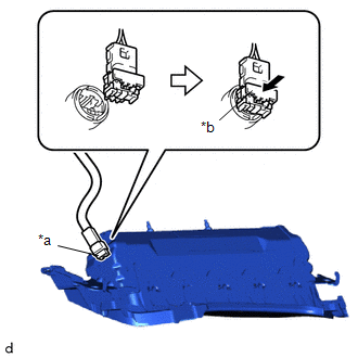
(d) Push in the airbag connector lock to install the airbag connector.
NOTICE:
Securely lock the airbag connector lock.
|
(e) Engage the hooks to temporarily install the lower No. 1 instrument panel airbag assembly with door. |
|
.png)
(f) Install the 2 bolts.
Torque:
10 N·m {102 kgf·cm, 7 ft·lbf}
NOTICE:
Confirm that the lower No. 1 instrument panel airbag assembly with door is installed securely without any excessive gaps and is not protruding outward.
3. INSTALL INSTRUMENT PANEL LOWER CENTER FINISH PANEL
Click here .gif)
4. INSTALL INSTRUMENT CLUSTER FINISH PANEL GARNISH ASSEMBLY
Click here
5. INSTALL FUSE BOX OPENING COVER
Click here
6. CONNECT CABLE TO NEGATIVE BATTERY TERMINAL
Click here
NOTICE:
When disconnecting the cable, some systems need to be initialized after the cable is reconnected.
Click here
7. PERFORM DIAGNOSTIC SYSTEM CHECK
Click here
8. INSPECT SRS WARNING LIGHT
Click here
 Disposal
DISPOSAL
CAUTION / NOTICE / HINT
CAUTION:
Before performing pre-disposal deployment of any SRS part, review and closely
follow all applicable environmental and hazardous material regulations. Pre ...

Other materials:
Toyota CH-R Service Manual > Safety Connect System: System Description
SYSTEM DESCRIPTION
DESCRIPTION
(a) Safety Connect performs ACN (Automatic Collision Notification), manual emergency
calling, stolen vehicle tracking and roadside assistance service by, audio and data
communications between the vehicle and call center through a cellular phone network.
As show ...
Toyota CH-R Service Manual > Can Communication System: Check Bus 1 Line for Short to GND
DESCRIPTION
There may be a short circuit between one of the CAN bus lines and GND when there
is no resistance between terminal 23 (CA1H) of the central gateway ECU (network
gateway ECU) and terminal 4 (CG) of the DLC3, or terminal 8 (CA1L) of the central
gateway ECU (network gateway ECU) and ...
Toyota C-HR (AX20) 2023-2026 Owner's Manual
Toyota CH-R Owners Manual
- For safety and security
- Instrument cluster
- Operation of each component
- Driving
- Interior features
- Maintenance and care
- When trouble arises
- Vehicle specifications
- For owners
Toyota CH-R Service Manual
- Introduction
- Maintenance
- Audio / Video
- Cellular Communication
- Navigation / Multi Info Display
- Park Assist / Monitoring
- Brake (front)
- Brake (rear)
- Brake Control / Dynamic Control Systems
- Brake System (other)
- Parking Brake
- Axle And Differential
- Drive Shaft / Propeller Shaft
- K114 Cvt
- 3zr-fae Battery / Charging
- Networking
- Power Distribution
- Power Assist Systems
- Steering Column
- Steering Gear / Linkage
- Alignment / Handling Diagnosis
- Front Suspension
- Rear Suspension
- Tire / Wheel
- Tire Pressure Monitoring
- Door / Hatch
- Exterior Panels / Trim
- Horn
- Lighting (ext)
- Mirror (ext)
- Window / Glass
- Wiper / Washer
- Door Lock
- Heating / Air Conditioning
- Interior Panels / Trim
- Lighting (int)
- Meter / Gauge / Display
- Mirror (int)
- Power Outlets (int)
- Pre-collision
- Seat
- Seat Belt
- Supplemental Restraint Systems
- Theft Deterrent / Keyless Entry

0.0086