Toyota CH-R Service Manual: Installation
INSTALLATION
CAUTION / NOTICE / HINT
HINT:
- Use the same procedure for the RH side and LH side.
- The following procedure is for the LH side.
PROCEDURE
1. INSTALL CURTAIN SHIELD AIRBAG ASSEMBLY
NOTICE:
When installing a curtain shield airbag assembly, have assistants hold it to prevent it from bending.
(a) Check that the ignition switch off.
(b) Check that the cable is disconnected from the negative (-) battery terminal.
CAUTION:
Wait at least 90 seconds after disconnecting the cable from the negative (-) battery terminal to disable the SRS system.
.png)
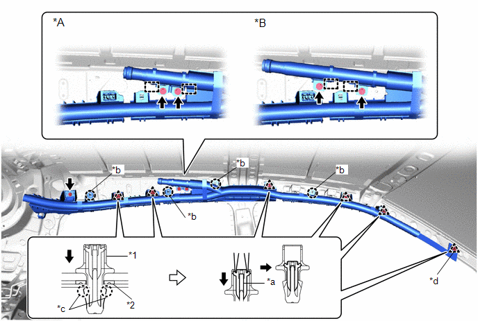
(c) Engage the hooks and claws (A) to temporarily install the curtain shield airbag assembly.
|
*A |
for Type A |
*B |
for Type B |
|
*1 |
Clip |
*2 |
Curtain Shield Airbag Clip Spacer |
|
*a |
Pin |
*b |
Claw (A) |
|
*c |
Claw (B) |
*d |
Spacer Location |
(d) Install the 3 new bolts.
Torque:
11 N·m {112 kgf·cm, 8 ft·lbf}
NOTICE:
Do not twist the curtain shield airbag assembly when installing it.
(e) Install the curtain shield airbag assembly with new spacer and new clip.
HINT:
Engage the claws (B) to install each new clip.
(f) Using needle nose pliers, push the pins into the clips.
NOTICE:
- Do not damage the pins.
- Make sure that the pins of the clips are pushed in firmly.
|
(g) Connect the airbag connector. NOTICE: When connecting any airbag connector, take care not to damage the airbag wire harness. |
|
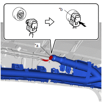
(h) Push in the airbag connector lock to install the airbag connector.
NOTICE:
Securely lock the airbag connector lock.
2. INSTALL ROOF HEADLINING ASSEMBLY
Click here .gif)
3. CONNECT CABLE TO NEGATIVE BATTERY TERMINAL
Click here
NOTICE:
When disconnecting the cable, some systems need to be initialized after the cable is reconnected.
Click here
4. PERFORM DIAGNOSTIC SYSTEM CHECK
Click here
5. INSPECT SRS WARNING LIGHT
Click here
 Disposal
DISPOSAL
CAUTION / NOTICE / HINT
CAUTION:
Before performing pre-disposal deployment of any SRS part, review and closely
follow all applicable environmental and hazardous material regulations. Pre ...

Other materials:
Toyota CH-R Service Manual > Front Drive Shaft Assembly: Components
COMPONENTS
ILLUSTRATION
*1
NO. 1 ENGINE UNDER COVER
*2
REAR ENGINE UNDER COVER LH
*3
REAR ENGINE UNDER COVER RH
-
-
N*m (kgf*cm, ft.*lbf): Specified torque
-
...
Toyota CH-R Service Manual > Front Lower Suspension Arm: Components
COMPONENTS
ILLUSTRATION
*1
NO. 1 ENGINE UNDER COVER
*2
REAR ENGINE UNDER COVER LH
N*m (kgf*cm, ft.*lbf): Specified torque
-
-
ILLUSTRATION
*1
FRONT LOWER NO. 1 SUSPENSIO ...
Toyota C-HR (AX20) 2023-2026 Owner's Manual
Toyota CH-R Owners Manual
- For safety and security
- Instrument cluster
- Operation of each component
- Driving
- Interior features
- Maintenance and care
- When trouble arises
- Vehicle specifications
- For owners
Toyota CH-R Service Manual
- Introduction
- Maintenance
- Audio / Video
- Cellular Communication
- Navigation / Multi Info Display
- Park Assist / Monitoring
- Brake (front)
- Brake (rear)
- Brake Control / Dynamic Control Systems
- Brake System (other)
- Parking Brake
- Axle And Differential
- Drive Shaft / Propeller Shaft
- K114 Cvt
- 3zr-fae Battery / Charging
- Networking
- Power Distribution
- Power Assist Systems
- Steering Column
- Steering Gear / Linkage
- Alignment / Handling Diagnosis
- Front Suspension
- Rear Suspension
- Tire / Wheel
- Tire Pressure Monitoring
- Door / Hatch
- Exterior Panels / Trim
- Horn
- Lighting (ext)
- Mirror (ext)
- Window / Glass
- Wiper / Washer
- Door Lock
- Heating / Air Conditioning
- Interior Panels / Trim
- Lighting (int)
- Meter / Gauge / Display
- Mirror (int)
- Power Outlets (int)
- Pre-collision
- Seat
- Seat Belt
- Supplemental Restraint Systems
- Theft Deterrent / Keyless Entry

0.012