Toyota CH-R Service Manual: Short in Driver Side Squib Circuit (B1800/51-B1803/51)
DESCRIPTION
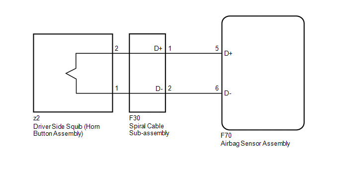
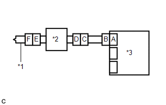
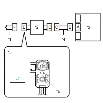
The driver side squib circuit consists of the airbag sensor assembly, spiral cable with sensor sub-assembly and horn button assembly.
The airbag sensor assembly uses this circuit to deploy the airbag when deployment conditions are met.
These DTCs are stored when a malfunction is detected in the driver side squib circuit.
|
DTC No. |
Detection Item |
DTC Detection Condition |
Trouble Area |
Test Mode / Check Mode |
|---|---|---|---|---|
|
B1800/51 |
Short in Driver Side Squib Circuit |
Any of the following conditions is met:
|
|
Applies to check mode |
|
B1801/51 |
Open in Driver Side Squib Circuit |
Any of the following conditions is met:
|
|
Applies to check mode |
|
B1802/51 |
Short to GND in Driver Side Squib Circuit |
Any of the following conditions is met:
|
|
Applies to check mode |
|
B1803/51 |
Short to B+ in Driver Side Squib Circuit |
Any of the following conditions is met:
|
|
Applies to check mode |
|
Vehicle Condition |
|||||
|---|---|---|---|---|---|
|
Pattern 1 |
Pattern 2 |
Pattern 3 |
Pattern 4 |
||
|
Diagnosis Condition |
Ignition switch ON |
○ |
○ |
○ |
○ |
|
Malfunction Status |
The airbag sensor assembly detects a line short in the driver side squib circuit during the primary check |
○ |
- |
- |
- |
|
Spiral cable with sensor sub-assembly malfunction |
- |
○ |
- |
- |
|
|
Driver side squib malfunction |
- |
- |
○ |
- |
|
|
Airbag sensor assembly malfunction |
- |
- |
- |
○ |
|
|
Detection Time |
- |
- |
- |
- |
|
|
Number of Trips |
1 trip |
1 trip |
1 trip |
1 trip |
|
|
Vehicle Condition |
|||||
|---|---|---|---|---|---|
|
Pattern 1 |
Pattern 2 |
Pattern 3 |
Pattern 4 |
||
|
Diagnosis Condition |
Ignition switch ON |
○ |
○ |
○ |
○ |
|
Malfunction Status |
The airbag sensor assembly detects an open in the driver side squib circuit |
○ |
- |
- |
- |
|
Spiral cable with sensor sub-assembly malfunction |
- |
○ |
- |
- |
|
|
Driver side squib malfunction |
- |
- |
○ |
- |
|
|
Airbag sensor assembly malfunction |
- |
- |
- |
○ |
|
|
Detection Time |
- |
- |
- |
- |
|
|
Number of Trips |
1 trip |
1 trip |
1 trip |
1 trip |
|
|
Vehicle Condition |
|||||
|---|---|---|---|---|---|
|
Pattern 1 |
Pattern 2 |
Pattern 3 |
Pattern 4 |
||
|
Diagnosis Condition |
Ignition switch ON |
○ |
○ |
○ |
○ |
|
Malfunction Status |
The airbag sensor assembly detects a short to ground in the driver side squib circuit |
○ |
- |
- |
- |
|
Spiral cable with sensor sub-assembly malfunction |
- |
○ |
- |
- |
|
|
Driver side squib malfunction |
- |
- |
○ |
- |
|
|
Airbag sensor assembly malfunction |
- |
- |
- |
○ |
|
|
Detection Time |
- |
- |
- |
- |
|
|
Number of Trips |
1 trip |
1 trip |
1 trip |
1 trip |
|
|
Vehicle Condition |
|||||
|---|---|---|---|---|---|
|
Pattern 1 |
Pattern 2 |
Pattern 3 |
Pattern 4 |
||
|
Diagnosis Condition |
Ignition switch ON |
○ |
○ |
○ |
○ |
|
Malfunction Status |
The airbag sensor assembly detects a short to B+ in the driver side squib circuit |
○ |
- |
- |
- |
|
Spiral cable with sensor sub-assembly malfunction |
- |
○ |
- |
- |
|
|
Driver side squib malfunction |
- |
- |
○ |
- |
|
|
Airbag sensor assembly malfunction |
- |
- |
- |
○ |
|
|
Detection Time |
- |
- |
- |
- |
|
|
Number of Trips |
1 trip |
1 trip |
1 trip |
1 trip |
|
HINT:
DTC will be output when conditions for either of the patterns in the table above are met.
WIRING DIAGRAM
CAUTION / NOTICE / HINT
NOTICE:
After turning the ignition switch off, waiting time may be required before disconnecting the cable from the negative (-) battery terminal. Therefore, make sure to read the disconnecting the cable from the negative (-) battery terminal notices before proceeding with work.
Click here .gif)
HINT:
- Perform the simulation method by selecting check mode (Signal Check)
using the Techstream.
Click here
- After selecting check mode (Signal Check), perform the simulation method
by wiggling each connector of the airbag system or driving the vehicle on
a city road or rough road.
Click here
PROCEDURE
|
1. |
CHECK VEHICLE CONDITION |
(a) Choose the model to be inspected.
|
Result |
Proceed to |
|---|---|
|
w/o Occupant Classification System |
A |
|
w/ Occupant Classification System |
B |
| B | .gif) |
GO TO STEP 8 |
|
.gif)
|
2. |
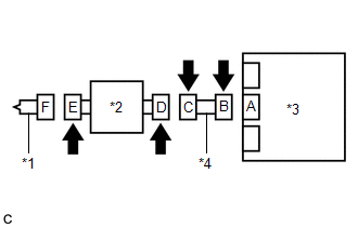
CHECK CONNECTORS |
|
(a) Turn the ignition switch off. |
|
(b) Disconnect the cable from the negative (-) battery terminal.
CAUTION:
Wait at least 90 seconds after disconnecting the cable from the negative (-) battery terminal to disable the SRS system.
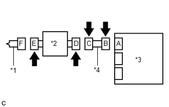
(c) Check that the connectors are properly connected to the horn button assembly, airbag sensor assembly and spiral cable with sensor sub-assembly.
OK:
The connectors are properly connected.
HINT:
If the connectors are not properly connected, reconnect the connectors and proceed to the next inspection.
(d) Disconnect the connectors from the horn button assembly, airbag sensor assembly and spiral cable with sensor sub-assembly.
(e) Check that the terminals of the connectors are not deformed or damaged.
OK:
The terminals are not deformed or damaged.
(f) Check that the spiral cable with sensor sub-assembly connector (on the horn button assembly side) is not loose, deformed or damaged.
OK:
The connector locking button is not disengaged, and the claw of the lock is not deformed or damaged.
(g) Check that the short springs of the activation prevention mechanisms of the instrument panel wire connector and spiral cable with sensor sub-assembly connector are not deformed or damaged.
OK:
The short springs are not deformed or damaged.
| NG | |
REPLACE WIRE HARNESS |
|
|
3. |
CHECK HORN BUTTON ASSEMBLY |
|
(a) Connect the instrument panel wire to the airbag sensor assembly and spiral cable with sensor sub-assembly. |
|
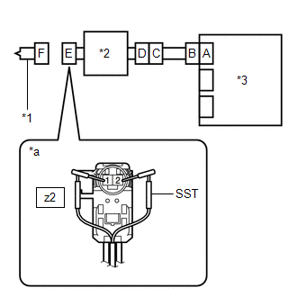
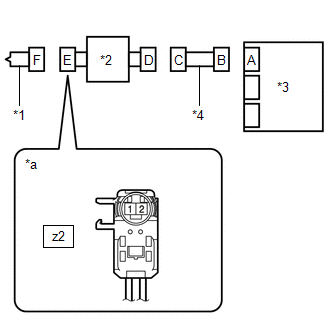
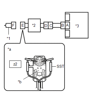
(b) Connect SST (resistance 2.1 Ω) to connector E.
CAUTION:
Never connect a tester to the horn button assembly for measurement, as this may lead to a serious injury due to airbag deployment.
NOTICE:
- Do not forcibly insert SST into the terminals of the connector when connecting it.
- Insert SST straight into the terminals of the connector.
SST: 09843-18061
(c) Connect the cable to the negative (-) battery terminal.
(d) Clear the DTCs stored in memory.
Click here
(e) Turn the ignition switch off.
(f) Turn the ignition switch ON, and wait for at least 60 seconds.
(g) Check for DTCs.
Click here
OK:
DTC B1800/51, B1801/51, B1802/51 or B1803/51 is not output.
HINT:
Codes other than DTCs B1800/51, B1801/51, B1802/51 and B1803/51 may be output at this time, but they are not related to this check.
(h) Turn the ignition switch off.
(i) Disconnect the cable from the negative (-) battery terminal.
CAUTION:
Wait at least 90 seconds after disconnecting the cable from the negative (-) battery terminal to disable the SRS system.
(j) Disconnect SST from connector E.
| OK | |
REPLACE HORN BUTTON ASSEMBLY |
|
|
4. |
CHECK DRIVER SIDE SQUIB CIRCUIT |
|
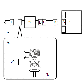
(a) Disconnect the instrument panel wire from the airbag sensor assembly. |
|
(b) Check for a short to B+ in the circuit.
(1) Connect the cable to the negative (-) battery terminal.
(2) Turn the ignition switch ON.
(3) Measure the voltage according to the value(s) in the table below.
Standard Voltage:
|
Tester Connection |
Switch Condition |
Specified Condition |
|---|---|---|
|
z2-2 - Body ground |
Ignition switch ON |
Below 1 V |
|
z2-1 - Body ground |
Ignition switch ON |
Below 1 V |
(4) Turn the ignition switch off.
(5) Disconnect the cable from the negative (-) battery terminal.
CAUTION:
Wait at least 90 seconds after disconnecting the cable from the negative (-) battery terminal to disable the SRS system.
(c) Check for an open in the circuit.
(1) Measure the resistance according to the value(s) in the table below.
Standard Resistance:
|
Tester Connection |
Condition |
Specified Condition |
|---|---|---|
|
z2-2 - z2-1 |
Always |
Below 1 Ω |
(d) Check for a short to ground in the circuit.
(1) Measure the resistance according to the value(s) in the table below.
Standard Resistance:
|
Tester Connection |
Condition |
Specified Condition |
|---|---|---|
|
z2-2 - Body ground |
Always |
1 MΩ or higher |
|
z2-1 - Body ground |
Always |
1 MΩ or higher |
(e) Check for a short in the circuit.
(1) Release the activation prevention mechanism built into connector B.
Click here
(2) Measure the resistance according to the value(s) in the table below.
Standard Resistance:
|
Tester Connection |
Condition |
Specified Condition |
|---|---|---|
|
z2-2 - z2-1 |
Always |
1 MΩ or higher |
(3) Restore the released activation prevention mechanism of connector B to the original condition.
| NG | |
GO TO STEP 6 |
|
|
5. |
CHECK DTC |
|
(a) Connect the connectors to the horn button assembly and airbag sensor assembly. |
|
(b) Connect the cable to the negative (-) battery terminal.
(c) Clear the DTCs stored in memory.
Click here
(d) Turn the ignition switch off.
(e) Turn the ignition switch ON, and wait for at least 60 seconds.
(f) Check for DTCs.
Click here
OK:
DTC B1800/51, B1801/51, B1802/51 or B1803/51 is not output.
HINT:
Codes other than DTCs B1800/51, B1801/51, B1802/51 and B1803/51 may be output at this time, but they are not related to this check.
| OK | |
USE SIMULATION METHOD TO CHECK |
| NG | |
REPLACE AIRBAG SENSOR ASSEMBLY |
|
6. |
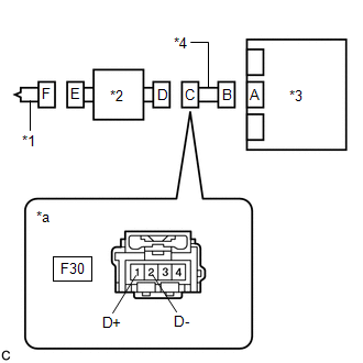
CHECK INSTRUMENT PANEL WIRE |
|
(a) Disconnect the instrument panel wire from the spiral cable with sensor sub-assembly. |
|
(b) Check for a short to B+ in the circuit.
(1) Connect the cable to the negative (-) battery terminal.
(2) Turn the ignition switch ON.
(3) Measure the voltage according to the value(s) in the table below.
Standard Voltage:
|
Tester Connection |
Switch Condition |
Specified Condition |
|---|---|---|
|
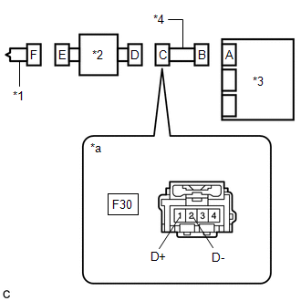
F30-1 (D+) - Body ground |
Ignition switch ON |
Below 1 V |
|
F30-2 (D-) - Body ground |
Ignition switch ON |
Below 1 V |
(4) Turn the ignition switch off.
(5) Disconnect the cable from the negative (-) battery terminal.
CAUTION:
Wait at least 90 seconds after disconnecting the cable from the negative (-) battery terminal to disable the SRS system.
(c) Check for an open in the circuit.
(1) Measure the resistance according to the value(s) in the table below.
Standard Resistance:
|
Tester Connection |
Condition |
Specified Condition |
|---|---|---|
|
F30-1 (D+) - F30-2 (D-) |
Always |
Below 1 Ω |
(d) Check for a short to ground in the circuit.
(1) Measure the resistance according to the value(s) in the table below.
Standard Resistance:
|
Tester Connection |
Condition |
Specified Condition |
|---|---|---|
|
F30-1 (D+) - Body ground |
Always |
1 MΩ or higher |
|
F30-2 (D-) - Body ground |
Always |
1 MΩ or higher |
(e) Check for a short in the circuit.
(1) Release the activation prevention mechanism built into connector B.
Click here
(2) Measure the resistance according to the value(s) in the table below.
Standard Resistance:
|
Tester Connection |
Condition |
Specified Condition |
|---|---|---|
|
F30-1 (D+) - F30-2 (D-) |
Always |
1 MΩ or higher |
(3) Restore the released activation prevention mechanism of connector B to the original condition.
| NG | |
REPLACE INSTRUMENT PANEL WIRE |
|
|
7. |
CHECK SPIRAL CABLE WITH SENSOR SUB-ASSEMBLY |
|
(a) Check for a short to B+ in the circuit. (1) Connect the cable to the negative (-) battery terminal. (2) Turn the ignition switch ON. (3) Measure the voltage according to the value(s) in the table below. Standard Voltage:
(4) Turn the ignition switch off. (5) Disconnect the cable from the negative (-) battery terminal. CAUTION: Wait at least 90 seconds after disconnecting the cable from the negative (-) battery terminal to disable the SRS system. |
|
(b) Check for an open in the circuit.
(1) Measure the resistance according to the value(s) in the table below.
Standard Resistance:
|
Tester Connection |
Condition |
Specified Condition |
|---|---|---|
|
z2-2 - z2-1 |
Always |
Below 1 Ω |
(c) Check for a short to ground in the circuit.
(1) Measure the resistance according to the value(s) in the table below.
Standard Resistance:
|
Tester Connection |
Condition |
Specified Condition |
|---|---|---|
|
z2-2 - Body ground |
Always |
1 MΩ or higher |
|
z2-1 - Body ground |
Always |
1 MΩ or higher |
(d) Check for a short in the circuit.
(1) Release the activation prevention mechanism built into connector D.
Click here
(2) Measure the resistance according to the value(s) in the table below.
Standard Resistance:
|
Tester Connection |
Condition |
Specified Condition |
|---|---|---|
|
z2-2 - z2-1 |
Always |
1 MΩ or higher |
(3) Restore the released activation prevention mechanism of connector D to the original condition.
| OK | |
USE SIMULATION METHOD TO CHECK |
| NG | |
REPLACE SPIRAL CABLE WITH SENSOR SUB-ASSEMBLY
|
|
8. |
CHECK CONNECTORS |
|
(a) Turn the ignition switch off. |
|
(b) Disconnect the cable from the negative (-) battery terminal.
CAUTION:
Wait at least 90 seconds after disconnecting the cable from the negative (-) battery terminal to disable the SRS system.
(c) Check that the connectors are properly connected to the horn button assembly, spiral cable with sensor sub-assembly and airbag sensor assembly.
OK:
The connectors are properly connected.
HINT:
If the connectors are not properly connected, reconnect the connectors and proceed to the next inspection.
(d) Disconnect the connectors from the horn button assembly, spiral cable with sensor sub-assembly and airbag sensor assembly.
(e) Check that the terminals of the connectors are not deformed or damaged.
OK:
The terminals are not deformed or damaged.
(f) Check that the spiral cable with sensor sub-assembly connector (on the horn button assembly side) is not loose, deformed or damaged.
OK:
The connector locking button is not disengaged, and the claw of the lock is not deformed or damaged.
(g) Check that the short springs of the activation prevention mechanisms of the instrument panel wire connector and spiral cable with sensor sub-assembly connector are not deformed or damaged.
OK:
The short springs are not deformed or damaged.
| NG | |
REPLACE WIRE HARNESS |
|
|
9. |
CHECK HORN BUTTON ASSEMBLY |
|
(a) Connect the instrument panel wire to the airbag sensor assembly and spiral cable with sensor sub-assembly. |
|
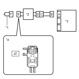
(b) Connect SST (resistance 2.1 Ω) to connector E (light green connector).
CAUTION:
Never connect a tester to the horn button assembly for measurement, as this may lead to a serious injury due to airbag deployment.
NOTICE:
- Do not forcibly insert SST into the terminals of the connector when connecting it.
- Insert SST straight into the terminals of the connector.
SST: 09843-18061
(c) Connect the cable to the negative (-) battery terminal.
(d) Clear the DTCs stored in memory.
Click here
(e) Turn the ignition switch off.
(f) Turn the ignition switch ON, and wait for at least 60 seconds.
(g) Check for DTCs.
Click here
OK:
DTC B1800/51, B1801/51, B1802/51 or B1803/51 is not output.
HINT:
Codes other than DTCs B1800/51, B1801/51, B1802/51 and B1803/51 may be output at this time, but they are not related to this check.
(h) Turn the ignition switch off.
(i) Disconnect the cable from the negative (-) battery terminal.
CAUTION:
Wait at least 90 seconds after disconnecting the cable from the negative (-) battery terminal to disable the SRS system.
(j) Disconnect SST from connector E.
| OK | |
REPLACE HORN BUTTON ASSEMBLY |
|
|
10. |
CHECK DRIVER SIDE SQUIB CIRCUIT |
|
(a) Disconnect the instrument panel wire from the airbag sensor assembly. |
|
(b) Check for a short to B+ in the circuit.
(1) Connect the cable to the negative (-) battery terminal.
(2) Turn the ignition switch ON.
(3) Measure the voltage according to the value(s) in the table below.
Standard Voltage:
|
Tester Connection |
Switch Condition |
Specified Condition |
|---|---|---|
|
z2-2 - Body ground |
Ignition switch ON |
Below 1 V |
|
z2-1 - Body ground |
Ignition switch ON |
Below 1 V |
(4) Turn the ignition switch off.
(5) Disconnect the cable from the negative (-) battery terminal.
CAUTION:
Wait at least 90 seconds after disconnecting the cable from the negative (-) battery terminal to disable the SRS system.
(c) Check for an open in the circuit.
(1) Measure the resistance according to the value(s) in the table below.
Standard Resistance:
|
Tester Connection |
Condition |
Specified Condition |
|---|---|---|
|
z2-2 - z2-1 |
Always |
Below 1 Ω |
(d) Check for a short to ground in the circuit.
(1) Measure the resistance according to the value(s) in the table below.
Standard Resistance:
|
Tester Connection |
Condition |
Specified Condition |
|---|---|---|
|
z2-2 - Body ground |
Always |
1 MΩ or higher |
|
z2-1 - Body ground |
Always |
1 MΩ or higher |
(e) Check for a short in the circuit.
(1) Release the activation prevention mechanism built into connector B.
Click here
(2) Measure the resistance according to the value(s) in the table below.
Standard Resistance:
|
Tester Connection |
Condition |
Specified Condition |
|---|---|---|
|
z2-2 - z2-1 |
Always |
1 MΩ or higher |
(3) Restore the released activation prevention mechanism of connector B to the original condition.
| NG | |
GO TO STEP 12 |
|
|
11. |
CHECK DTC |
|
(a) Connect the connectors to the horn button assembly and airbag sensor assembly. |
|
(b) Connect the cable to the negative (-) battery terminal.
(c) Clear the DTCs stored in memory.
Click here
(d) Turn the ignition switch off.
(e) Turn the ignition switch ON, and wait for at least 60 seconds.
(f) Check for DTCs.
Click here
OK:
DTC B1800/51, B1801/51, B1802/51 or B1803/51 is not output.
HINT:
Codes other than DTCs B1800/51, B1801/51, B1802/51 and B1803/51 may be output at this time, but they are not related to this check.
| OK | |
USE SIMULATION METHOD TO CHECK |
| NG | |
REPLACE AIRBAG SENSOR ASSEMBLY |
|
12. |
CHECK INSTRUMENT PANEL WIRE |
|
(a) Disconnect the instrument panel wire from the spiral cable with sensor sub-assembly. |
|
(b) Check for a short to B+ in the circuit.
(1) Connect the cable to the negative (-) battery terminal.
(2) Turn the ignition switch ON.
(3) Measure the voltage according to the value(s) in the table below.
Standard Voltage:
|
Tester Connection |
Switch Condition |
Specified Condition |
|---|---|---|
|
F30-1 (D+) - Body ground |
Ignition switch ON |
Below 1 V |
|
F30-2 (D-) - Body ground |
Ignition switch ON |
Below 1 V |
(4) Turn the ignition switch off.
(5) Disconnect the cable from the negative (-) battery terminal.
CAUTION:
Wait at least 90 seconds after disconnecting the cable from the negative (-) battery terminal to disable the SRS system.
(c) Check for an open in the circuit.
(1) Measure the resistance according to the value(s) in the table below.
Standard Resistance:
|
Tester Connection |
Condition |
Specified Condition |
|---|---|---|
|
F30-1 (D+) - F30-2 (D-) |
Always |
Below 1 Ω |
(d) Check for a short to ground in the circuit.
(1) Measure the resistance according to the value(s) in the table below.
Standard Resistance:
|
Tester Connection |
Condition |
Specified Condition |
|---|---|---|
|
F30-1 (D+) - Body ground |
Always |
1 MΩ or higher |
|
F30-2 (D-) - Body ground |
Always |
1 MΩ or higher |
(e) Check for a short in the circuit.
(1) Release the activation prevention mechanism built into connector B.
Click here
(2) Measure the resistance according to the value(s) in the table below.
Standard Resistance:
|
Tester Connection |
Condition |
Specified Condition |
|---|---|---|
|
F30-1 (D+) - F30-2 (D-) |
Always |
1 MΩ or higher |
(3) Restore the released activation prevention mechanism of connector B to the original condition.
| NG | |
REPLACE INSTRUMENT PANEL WIRE |
|
|
13. |
CHECK SPIRAL CABLE WITH SENSOR SUB-ASSEMBLY |
|
(a) Check for a short to B+ in the circuit. (1) Connect the cable to the negative (-) battery terminal. (2) Turn the ignition switch ON. (3) Measure the voltage according to the value(s) in the table below. Standard Voltage:
(4) Turn the ignition switch off. (5) Disconnect the cable from the negative (-) battery terminal. CAUTION: Wait at least 90 seconds after disconnecting the cable from the negative (-) battery terminal to disable the SRS system. |
|
(b) Check for an open in the circuit.
(1) Measure the resistance according to the value(s) in the table below.
Standard Resistance:
|
Tester Connection |
Condition |
Specified Condition |
|---|---|---|
|
z2-2 - z2-1 |
Always |
Below 1 Ω |
(c) Check for a short to ground in the circuit.
(1) Measure the resistance according to the value(s) in the table below.
Standard Resistance:
|
Tester Connection |
Condition |
Specified Condition |
|---|---|---|
|
z2-2 - Body ground |
Always |
1 MΩ or higher |
|
z2-1 - Body ground |
Always |
1 MΩ or higher |
(d) Check for a short in the circuit.
(1) Release the activation prevention mechanism built into connector D.
Click here
(2) Measure the resistance according to the value(s) in the table below.
Standard Resistance:
|
Tester Connection |
Condition |
Specified Condition |
|---|---|---|
|
z2-2 - z2-1 |
Always |
1 MΩ or higher |
(3) Restore the released activation prevention mechanism of connector D to the original condition.
| OK | |
USE SIMULATION METHOD TO CHECK |
| NG | |
REPLACE SPIRAL CABLE WITH SENSOR SUB-ASSEMBLY
|
 Front Door Pressure Sensor LH (B167A/5A,B167E/5A)
DESCRIPTION
The side collision sensor LH circuit (bus 1) consists of the airbag sensor assembly,
door side airbag sensor LH, No. 1 side airbag sensor LH and No. 2 side airbag sensor
LH.
The door ...
 Short in Driver Side Squib 2nd Step Circuit (B1810/53-B1813/53)
DESCRIPTION
The driver side squib 2nd step circuit consists of the airbag sensor assembly,
spiral cable with sensor sub-assembly and horn button assembly.
The airbag sensor assembly uses this circ ...
Other materials:
Toyota CH-R Service Manual > Lighting (ext): Relay
On-vehicle Inspection
ON-VEHICLE INSPECTION
PROCEDURE
1. INSPECT FOG FR RELAY
(a) Check the resistance.
(1) Measure the resistance according to the value(s) in the table below.
Standard Resistance:
Tester Connection
Condition
...
Toyota CH-R Service Manual > Charging System: Freeze Frame Data
FREEZE FRAME DATA
DESCRIPTION
The ECM records vehicle and driving condition information as freeze frame data
the moment a DTC is stored. When troubleshooting, freeze frame data can be helpful
in determining whether the vehicle was moving or stationary, whether the engine
was warmed up or not ...
Toyota C-HR (AX20) 2023-2026 Owner's Manual
Toyota CH-R Owners Manual
- For safety and security
- Instrument cluster
- Operation of each component
- Driving
- Interior features
- Maintenance and care
- When trouble arises
- Vehicle specifications
- For owners
Toyota CH-R Service Manual
- Introduction
- Maintenance
- Audio / Video
- Cellular Communication
- Navigation / Multi Info Display
- Park Assist / Monitoring
- Brake (front)
- Brake (rear)
- Brake Control / Dynamic Control Systems
- Brake System (other)
- Parking Brake
- Axle And Differential
- Drive Shaft / Propeller Shaft
- K114 Cvt
- 3zr-fae Battery / Charging
- Networking
- Power Distribution
- Power Assist Systems
- Steering Column
- Steering Gear / Linkage
- Alignment / Handling Diagnosis
- Front Suspension
- Rear Suspension
- Tire / Wheel
- Tire Pressure Monitoring
- Door / Hatch
- Exterior Panels / Trim
- Horn
- Lighting (ext)
- Mirror (ext)
- Window / Glass
- Wiper / Washer
- Door Lock
- Heating / Air Conditioning
- Interior Panels / Trim
- Lighting (int)
- Meter / Gauge / Display
- Mirror (int)
- Power Outlets (int)
- Pre-collision
- Seat
- Seat Belt
- Supplemental Restraint Systems
- Theft Deterrent / Keyless Entry

0.0088