Toyota CH-R Service Manual: Vehicle Control History
VEHICLE CONTROL HISTORY
Function Overview
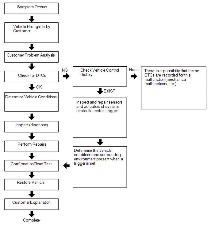
(a) The vehicle control history is a function that records control data (record data) when triggered by specific vehicle behavior. When DTCs are not detected according to information provided by customers, by checking the vehicle control history, it is possible to gain a quantitative grasp on diagnostic information and the history can be used as a reference to proceed with malfunction diagnosis.
(b) The vehicle control history also stores image data when a specific trigger is set.
(c) The vehicle control history is recorded in different storage areas designated by trigger group and it is possible to save up to 140 items in total. If storage space runs out, the data is cleared from the oldest data first for the respective storage area and new data is recorded.
(d) Each trigger receives time information from the main body ECU (time elapsed since ignition switch turned ON) or the navigation system* (absolute time).
- *: Only for factory-installed navigation systems (factory option)
(e) Data is recorded in the airbag sensor assembly EEPROM. Even if the negative (-) battery terminal is disconnected, the vehicle control history does not disappear. Also, data cannot be cleared using the Techstream.
(f) The image data is stored in the camera sensor EEPROM.
Notices for Use
(a) Vehicle control history is used as support information during malfunction diagnosis for each system and cannot be used to determine the actual cause of a problem.
(b) Judgment of each trigger is based on signals from sensors and actuators (recognition value of each ECU). Therefore, make sure to inspect and adjust systems related to each trigger when using the vehicle control history.
Basic Flow
Trigger Item
(a) Connect the Techstream to the DLC3.
(b) Turn the ignition switch ON.
(c) Using the Techstream, enter the following menus: Body Electrical / SRS Airbag / Utility / Vehicle Control History.
Body Electrical > SRS Airbag > Utility|
Tester Display |
|---|
|
Vehicle Control History |
|
Related System |
Storage Area Group (storage limit) |
Trigger Item Name |
Trigger Description |
Image Recording |
Remarks |
|---|---|---|---|---|---|
|
Engine control/Hybrid control/Automatic transmission |
Area 2 (Approximately 42 times) |
Accelerator pedal opening angle signal is high during low speed |
An accelerator high position signal condition continues for a certain period of time while in the low speed range. |
- |
- |
|
Accelerator pedal opening angle signal is high immediately after brake pedal is released |
An accelerator high position signal is received while in the low speed range after there is a change from brake input condition to brake and accelerator pedal released condition. |
- |
- |
||
|
Area 7 (Approximately 12 times) |
Accelerator high position in mid to high speed |
An accelerator high position signal condition continues for a certain period of time while in the mid to high speed range. |
- |
- |
|
|
Engine control/Hybrid control/Automatic transmission |
Area 3 (Approximately 40 times) |
Accelerator pedal opening angle is medium or higher immediately after shifting to R |
An accelerator mid to high position signal is received while in the low speed range immediately after the shift lever is moved to R during an accelerator low position signal condition. |
- |
Excluding hybrid vehicles |
|
Accelerator pedal opening angle is medium or higher immediately after shifting to forward position |
An accelerator mid to high position signal is received while in the low speed range immediately after the shift lever is moved to a forward position (a position other than P, N or R) during an accelerator low position signal condition. |
- |
Excluding hybrid vehicles |
||
|
Accelerator pedal opening angle is medium or higher immediately after shifting to driving position |
An accelerator mid to high position signal is received while in the low speed range immediately after the shift lever is moved to a driving position (a position other than P or N) during an accelerator low position signal condition. |
- |
Only hybrid vehicles |
||
|
R position signal input during medium or higher accelerator signal input |
An accelerator mid to high position signal condition while the shift lever is in R continues for a certain period of time after the shift lever is moved to R during an accelerator mid to high position signal condition. |
- |
Excluding hybrid vehicles |
||
|
Forward position signal input during medium or higher accelerator signal input |
An accelerator mid to high position signal condition continues for a certain period of time while in a forward position (a position other than P, N or R) after shifting to a forward position (a position other than P, N, or R) during an accelerator mid to high position signal condition. |
- |
Excluding hybrid vehicles |
||
|
Engine control/Hybrid control/Automatic transmission |
Area 3 (Approximately 40 times) |
Driving position signal input during medium or higher accelerator signal input |
The shift lever is moved to a driving position (a position other than P or N) during an accelerator mid to high position signal condition. |
- |
Only hybrid vehicles |
|
Accelerator signal and brake signal input simultaneously |
An accelerator mid to high position signal condition and brake input condition simultaneously continue for a certain period of time. |
- |
- |
||
|
Medium or higher accelerator signal input immediately after switching to D or R |
The shift lever is moved to D (or R) during an accelerator low signal condition after the shift lever is moved to R (or D). After that, an accelerator mid to high position signal is received. |
- |
- |
||
|
Medium or higher accelerator signal input during N |
An accelerator mid to high position signal is received while in a low speed range after the shift lever is moved to N. |
- |
- |
||
|
Brake control |
Area 5 (Approximately 5 times) |
VSC operation history |
When VSC operation starts. |
- |
Only for vehicles with VSC |
|
TRC operation history |
When TRC operation starts. |
- |
Only for vehicles with TRC |
||
|
ABS operation history |
When ABS operation starts. |
- |
- |
||
|
Area 1 (Approximately 4 times) |
Sudden braking history |
Detects forward and backward acceleration above a certain level. |
- |
Only for vehicles with VSC |
|
|
Sudden turning history |
Detects lateral acceleration above a certain level. |
- |
Only for vehicles with VSC |
||
|
Cruise control |
Area 4 (Approximately 15 times) |
Accelerator pedal opening angle signal is high during cruise control operation |
An accelerator high position signal condition continues for a certain period of time during cruise control. |
- |
Only for vehicles with cruise control |
|
Pre-collision |
Area 6 (Approximately 6 times) |
PCS operation history (warning buzzer operation) |
PCS (warning buzzer) operates. |
- |
Only for vehicles with PCS |
|
PCS operation history (warning brake operation) |
PCS (brake alarm) operates. |
- |
Only for vehicles with PCS (w/ Driver Monitor Camera) |
||
|
PCS operation history (pre-collision brake assist operation) |
PCS (PCS brake assist) operates. |
○ |
|
||
|
PCS operation history (prior brake operation) |
PCS (preliminary braking) operates. |
○ |
Only for vehicles with PCS |
||
|
PCS operation history (pre-collision brake operation) |
PCS (PCS brake) operates. |
○ |
Only for vehicles with PCS |
||
|
PCS operation history (pre-collision seat belt operation) |
PCS (PCS seat belt) operates. |
- |
Only for vehicles with PCS |
||
|
PCS operation history (pre-pump operation) |
PCS (PCS brake assist standby) operates. |
- |
Only for vehicles with PCS |
||
|
PCS operation history (PBR operation) |
PCS (stop light illumination) operates. |
- |
Only for vehicles with PCS |
||
|
PCS operation history (PBH operation) |
PCS (after operation brake hold) operates. |
- |
Only for vehicles with PCS |
||
|
PCS operation history (avoidance support) |
PCS (evasion support) operates. |
- |
Only for vehicles with PCS |
||
|
PCS operation history (when acceleration above certain amount is detected) |
Forward and backward acceleration above a certain amount is detected. |
- |
Only for vehicles with PCS |
||
|
Lane departure alert/Lane-keeping assist |
Area 8 (Approximately 6 times) |
Torque sensor signal above certain amount is detected during LKA/LDA operation |
When the LKA/LDA system is ON, a torque sensor signal above a certain amount is detected. |
- |
Only for vehicles with LKA/LDA (w/ Steering Control) |
|
Intelligent clearance sonar |
Area 9 (Approximately 6 times) |
ICS operation history (output limit) |
ICS (output restriction) operates. |
- |
Only for vehicles with ICS |
|
ICS operation history (max output limit) |
ICS (maximum output restriction) operates. |
- |
Only for vehicles with ICS |
||
|
ICS operation history (brake control) |
ICS (brake control) operates. |
- |
Only for vehicles with ICS |
||
|
ICS operation history (stop) |
ICS (vehicle stop) operates. |
- |
Only for vehicles with ICS |
||
|
ICS operation history (regression) |
ICS (return) operates. |
- |
Only for vehicles with ICS |
||
|
ICS operation history (temporarily not available) |
ICS is temporarily not available. |
- |
Only for vehicles with ICS |
Record Data Items
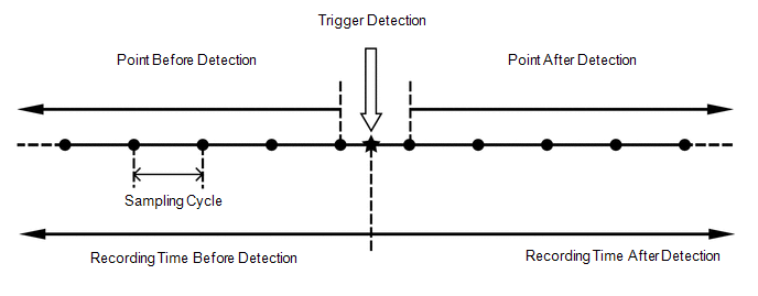
(a) When a trigger is detected, the vehicle status (ECU data) before and after the trigger are simultaneously recorded as record data.
(b) Recording time and record data differ for each trigger.
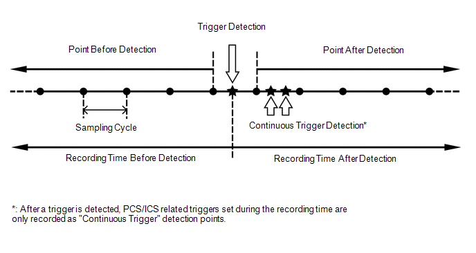
(c) The sampling cycle and recording time for the record data and image data is not always the same.
When not "PCS/ICS Operation History"
When "PCS/ICS Operation History"
 Record Data Specifications
|
Trigger Item |
Record Data |
|||||
|---|---|---|---|---|---|---|
|
Before Detection |
After Detection |
Sampling Cycle (sec.) |
||||
|
ID No. |
Item |
Recording Time (sec.) |
Number of Points |
Recording Time (sec.) |
Number of Points |
|
|
2 |
Accelerator pedal opening angle signal is high during low speed |
7.5 |
15 |
7.5 |
16 |
0.5 |
|
3 |
Accelerator high position in mid to high speed |
7.5 |
15 |
7.5 |
16 |
0.5 |
|
4 |
Accelerator pedal opening angle signal is high immediately after brake pedal is released |
7.5 |
15 |
7.5 |
16 |
0.5 |
|
5-1 |
Accelerator pedal opening angle is medium or higher immediately after shifting to R |
5 |
10 |
5 |
11 |
0.5 |
|
5-2 |
Accelerator pedal opening angle is medium or higher immediately after shifting to forward position |
|||||
|
5-3 |
Accelerator pedal opening angle is medium or higher immediately after shifting to driving position |
|||||
|
6-1 |
R position signal input during medium or higher accelerator signal input |
5 |
10 |
5 |
11 |
0.5 |
|
6-2 |
Forward position signal input during medium or higher accelerator signal input |
|||||
|
6-3 |
Driving position signal input during medium or higher accelerator signal input |
|||||
|
8 |
Accelerator signal and brake signal input simultaneously |
5 |
10 |
5 |
11 |
0.5 |
|
9 |
Medium or higher accelerator signal input immediately after switching to D or R |
5 |
10 |
5 |
11 |
0.5 |
|
10 |
Medium or higher accelerator signal input during N |
5 |
10 |
5 |
11 |
0.5 |
|
12 |
VSC operation history |
5 |
34 |
5 |
35 |
0.15 |
|
13 |
TRC operation history |
5 |
34 |
5 |
35 |
0.15 |
|
14 |
ABS operation history |
5 |
34 |
5 |
35 |
0.15 |
|
15 |
Sudden braking history |
5 |
34 |
5 |
35 |
0.15 |
|
16 |
Sudden turning history |
5 |
34 |
5 |
35 |
0.15 |
|
17 |
Accelerator pedal opening angle signal is high during cruise control operation |
5 |
10 |
5 |
11 |
0.5 |
|
18-1 |
PCS operation history (warning buzzer operation) |
5 |
10 |
4 |
9 |
0.5 |
|
18-2 |
PCS operation history (warning brake operation) |
|||||
|
18-3 |
PCS operation history (pre-collision brake assist operation) |
|||||
|
18-4 |
PCS operation history (prior brake operation) |
|||||
|
18-5 |
PCS operation history (pre-collision brake operation) |
|||||
|
18-6 |
PCS operation history (pre-collision seat belt operation) |
|||||
|
18-7 |
PCS operation history (pre-pump operation) |
|||||
|
18-8 |
PCS operation history (PBR operation) |
|||||
|
18-9 |
PCS operation history (PBH operation) |
|||||
|
18-10 |
PCS operation history (avoidance support) |
|||||
|
18-11 |
PCS operation history (when acceleration above certain amount is detected) |
|||||
|
19 |
Torque sensor signal above certain amount is detected during LKA/LDA operation |
8 |
40 |
0 |
1 |
0.2 |
|
20-1 |
ICS operation history (output limit) |
5 |
10 |
5 |
11 |
0.5 |
|
20-2 |
ICS operation history (max output limit) |
|||||
|
20-3 |
ICS operation history (brake control) |
|||||
|
20-4 |
ICS operation history (stop) |
|||||
|
20-5 |
ICS operation history (regression) |
|||||
|
20-6 |
ICS operation history (temporarily not available) |
|||||
|
Trigger Item |
Record Data |
|||||
|---|---|---|---|---|---|---|
|
Before Detection |
After Detection |
Sampling Cycle (sec.) |
||||
|
ID No. |
Item |
Recording Time (sec.) |
Number of Points |
Recording Time (sec.) |
Number of Points |
|
|
18-3 |
PCS operation history (pre-collision brake assist operation) |
6 |
10 |
6 |
10 |
0.6 |
|
18-4 |
PCS operation history (prior brake operation) |
|||||
|
18-5 |
PCS operation history (pre-collision brake operation) |
|||||
|
Item Name |
Trigger ID No. |
|---|---|
|
Vehicle Speed |
2, 4, 3, 5-1, 5-2, 5-3, 6-1, 6-2, 6-3, 8, 9, 10, 12, 13, 14, 15, 16, 17, 18-1, 18-2, 18-3, 18-4, 18-5, 18-6, 18-7, 18-8, 18-9, 18-10, 18-11, 19, 20-1, 20-2, 20-3, 20-4, 20-5, 20-6 |
|
Accelerator Opening Ratio |
2, 4, 3, 5-1, 5-2, 5-3, 6-1, 6-2, 6-3, 8, 9, 10, 12, 13, 14, 15, 16, 17, 18-1, 18-2, 18-3, 18-4, 18-5, 18-6, 18-7, 18-8, 18-9, 18-10, 18-11, 19, 20-1, 20-2, 20-3, 20-4, 20-5, 20-6 |
|
Engine RPM Data |
2, 4, 3, 5-1, 5-2, 5-3, 6-1, 6-2, 6-3, 8, 9, 10, 12, 13, 14, 15, 16, 17, 18-1, 18-2, 18-3, 18-4, 18-5, 18-6, 18-7, 18-8, 18-9, 18-10, 18-11, 19, 20-1, 20-2, 20-3, 20-4, 20-5, 20-6 |
|
Cruise Control |
2, 4, 3, 5-1, 5-2, 5-3, 6-1, 6-2, 6-3, 8, 9, 10, 12, 13, 14, 15, 16, 17, 18-1, 18-2, 18-3, 18-4, 18-5, 18-6, 18-7, 18-8, 18-9, 18-10, 18-11, 19, 20-1, 20-2, 20-3, 20-4, 20-5, 20-6 |
|
Shift Position Signal |
2, 4, 3, 5-1, 5-2, 5-3, 6-1, 6-2, 6-3, 8, 9, 10, 12, 13, 14, 15, 16, 17, 18-1, 18-2, 18-3, 18-4, 18-5, 18-6, 18-7, 18-8, 18-9, 18-10, 18-11, 19, 20-1, 20-2, 20-3, 20-4, 20-5, 20-6 |
|
Brake SW |
2, 4, 3, 5-1, 5-2, 5-3, 6-1, 6-2, 6-3, 8, 9, 10, 12, 13, 14, 15, 16, 17, 18-1, 18-2, 18-3, 18-4, 18-5, 18-6, 18-7, 18-8, 18-9, 18-10, 18-11, 19, 20-1, 20-2, 20-3, 20-4, 20-5, 20-6 |
|
Brake Oil Pressure |
2, 4, 3, 5-1, 5-2, 5-3, 6-1, 6-2, 6-3, 8, 9, 10, 12, 13, 14, 15, 16, 17, 18-1, 18-2, 18-3, 18-4, 18-5, 18-6, 18-7, 18-8, 18-9, 18-10, 18-11, 19, 20-1, 20-2, 20-3, 20-4, 20-5, 20-6 |
|
Yaw Rate Sensor Signal |
2, 4, 3, 5-1, 5-2, 5-3, 6-1, 6-2, 6-3, 8, 9, 10, 12, 13, 14, 15, 16, 17, 18-1, 18-2, 18-3, 18-4, 18-5, 18-6, 18-7, 18-8, 18-9, 18-10, 18-11, 19, 20-1, 20-2, 20-3, 20-4, 20-5, 20-6 |
|
Longitudinal G Sensor Signal |
2, 4, 3, 5-1, 5-2, 5-3, 6-1, 6-2, 6-3, 8, 9, 10, 12, 13, 14, 15, 16, 17, 18-1, 18-2, 18-3, 18-4, 18-5, 18-6, 18-7, 18-8, 18-9, 18-10, 18-11, 19, 20-1, 20-2, 20-3, 20-4, 20-5, 20-6 |
|
Lateral G Sensor Signal |
2, 4, 3, 5-1, 5-2, 5-3, 6-1, 6-2, 6-3, 8, 9, 10, 12, 13, 14, 15, 16, 17, 18-1, 18-2, 18-3, 18-4, 18-5, 18-6, 18-7, 18-8, 18-9, 18-10, 18-11, 19, 20-1, 20-2, 20-3, 20-4, 20-5, 20-6 |
|
Throttle Opening Ratio |
2, 4, 3, 5-1, 5-2, 5-3, 6-1, 6-2, 6-3, 8, 9, 10, 12, 13, 14, 15, 16, 17, 18-1, 18-2, 18-3, 18-4, 18-5, 18-6, 18-7, 18-8, 18-9, 18-10, 18-11, 19, 20-1, 20-2, 20-3, 20-4, 20-5, 20-6 |
|
Command Value of Fuel Injection Amount |
2, 4, 3, 5-1, 5-2, 5-3, 6-1, 6-2, 6-3, 8, 9, 10, 12, 13, 14, 15, 16, 17, 18-1, 18-2, 18-3, 18-4, 18-5, 18-6, 18-7, 18-8, 18-9, 18-10, 18-11, 19, 20-1, 20-2, 20-3, 20-4, 20-5, 20-6 |
|
Steering Signal |
2, 4, 3, 5-1, 5-2, 5-3, 6-1, 6-2, 6-3, 8, 9, 10, 12, 13, 14, 15, 16, 17, 18-1, 18-2, 18-3, 18-4, 18-5, 18-6, 18-7, 18-8, 18-9, 18-10, 18-11, 19, 20-1, 20-2, 20-3, 20-4, 20-5, 20-6 |
|
ICS Received Data Invalid Flag |
20-1, 20-2, 20-3, 20-4, 20-5, 20-6 |
|
ICS Trigger Flag |
20-1, 20-2, 20-3, 20-4, 20-5, 20-6 |
|
ICS Temporarily Not Available (Dirt) |
20-1, 20-2, 20-3, 20-4, 20-5, 20-6 |
|
ICS Temporarily Not Available (Low Voltage) |
20-1, 20-2, 20-3, 20-4, 20-5, 20-6 |
|
ICS Request Driving Force Control Flag |
20-1, 20-2, 20-3, 20-4, 20-5, 20-6 |
|
ICS Request Braking Control Flag |
20-1, 20-2, 20-3, 20-4, 20-5, 20-6 |
|
ICS Controlled Object Distance |
20-1, 20-2, 20-3, 20-4, 20-5, 20-6 |
|
ICS Controlled Object 1 Position (X) |
20-1, 20-2, 20-3, 20-4, 20-5, 20-6 |
|
ICS Controlled Object 1 Position (Y) |
20-1, 20-2, 20-3, 20-4, 20-5, 20-6 |
|
ICS Recognition Sensor (Controlled Object 1) |
20-1, 20-2, 20-3, 20-4, 20-5, 20-6 |
|
ICS Recognition Level (Controlled Object 1) |
20-1, 20-2, 20-3, 20-4, 20-5, 20-6 |
|
ICS Controlled Object 2 Position (X) |
20-1, 20-2, 20-3, 20-4, 20-5, 20-6 |
|
ICS Controlled Object 2 Position (Y) |
20-1, 20-2, 20-3, 20-4, 20-5, 20-6 |
|
ICS Recognition Sensor (Controlled Object 2) |
20-1, 20-2, 20-3, 20-4, 20-5, 20-6 |
|
ICS Recognition Level (Controlled Object 2) |
20-1, 20-2, 20-3, 20-4, 20-5, 20-6 |
|
ICS Controlled Object 3 Position (X) |
20-1, 20-2, 20-3, 20-4, 20-5, 20-6 |
|
ICS Controlled Object 3 Position (Y) |
20-1, 20-2, 20-3, 20-4, 20-5, 20-6 |
|
ICS Recognition Sensor (Controlled Object 3) |
20-1, 20-2, 20-3, 20-4, 20-5, 20-6 |
|
ICS Recognition Level (Controlled Object 3) |
20-1, 20-2, 20-3, 20-4, 20-5, 20-6 |
|
Power Train Mode |
2, 4, 3, 5-1, 5-2, 5-3, 6-1, 6-2, 6-3, 8, 9, 10, 12, 13, 15, 16 |
|
SNOW Mode |
2, 4, 3, 5-1, 5-2, 5-3, 6-1, 6-2, 6-3, 8, 9, 10, 12, 13, 15, 16 |
|
Valid/Invalid of Driving Mode |
2, 4, 3, 5-1, 5-2, 5-3, 6-1, 6-2, 6-3, 8, 9, 10, 12, 13, 15, 16 |
|
VSC OFF Lamp |
2, 4, 3, 5-1, 5-2, 5-3, 6-1, 6-2, 6-3, 8, 9, 10, 12, 13, 15, 16 |
|
TRC OFF Lamp |
2, 4, 3, 5-1, 5-2, 5-3, 6-1, 6-2, 6-3, 8, 9, 10, 12, 13, 15, 16 |
|
Valid/Invalid of TRC/VSC OFF Lamp |
2, 4, 3, 5-1, 5-2, 5-3, 6-1, 6-2, 6-3, 8, 9, 10, 12, 13, 15, 16 |
|
EV Mode |
2, 4, 3, 5-1, 5-2, 5-3, 6-1, 6-2, 6-3, 8, 9, 10, 12, 13, 15, 16 |
|
Valid/Invalid of EV Mode |
2, 4, 3, 5-1, 5-2, 5-3, 6-1, 6-2, 6-3, 8, 9, 10, 12, 13, 15, 16 |
|
Shift Gear |
2, 4, 3, 5-1, 5-2, 5-3, 6-1, 6-2, 6-3, 8, 9, 10, 12, 13, 15, 16 |
|
Engine Load Factor |
2, 4, 3, 5-1, 5-2, 5-3, 6-1, 6-2, 6-3, 8, 9, 10 |
|
READY Signal |
2, 4, 3, 5-1, 5-2, 5-3, 6-1, 6-2, 6-3, 8, 9, 10, 12, 13, 15, 16 |
|
Gear Position Signal |
2, 4, 3, 5-1, 5-2, 5-3, 6-1, 6-2, 6-3, 8, 9, 10, 15, 16 |
|
Turbine RPM/Input Shaft RPM |
2, 4, 3, 5-1, 5-2, 5-3, 6-1, 6-2, 6-3, 8, 9, 10, 15, 16 |
|
Under VSC Control |
12, 13, 14, 15, 16 |
|
Under ABS Control |
12, 13, 14, 15, 16 |
|
Under VDM Control |
12, 13, 14, 15, 16 |
|
Under TRC Operation Flag |
12, 13, 14, 15, 16 |
|
FR Wheel Speed |
12, 13, 14, 15, 16 |
|
FL Wheel Speed |
12, 13, 14, 15, 16 |
|
RR Wheel Speed |
12, 13, 14, 15, 16 |
|
RL Wheel Speed |
12, 13, 14, 15, 16 |
|
Cruise System |
17 |
|
Driving Force Demand Judgment Flag |
17 |
|
Cruise Control Master Switch Flag |
17 |
|
DSS Judgment Flag |
17 |
|
Cruise Control Res/Accel SW |
17 |
|
Cruise Control Set/Coast SW |
17 |
|
Cruise Control Cancel SW |
17 |
|
Cruise Control Brake SW |
17 |
|
Cruise Control D Signal |
17 |
|
Cruise Control Main SW |
17 |
|
Cruise Control Set Speed |
17 |
|
Vehicle Speed (during Cruise Control) |
17 |
|
Cruise Control Request Value |
17 |
|
ACC Target Distance |
17 |
|
ACC Target Condition |
17 |
|
ACC Relative Speed |
17 |
|
PCS Reception Data Invalid Flag |
18-1, 18-2, 18-3, 18-4, 18-5, 18-6, 18-7, 18-8, 18-9, 18-10, 18-11 |
|
ALM Request Flag 2 |
18-1, 18-2, 18-3, 18-4, 18-5, 18-6, 18-7, 18-8, 18-9, 18-10, 18-11 |
|
ALM Request Flag |
18-1, 18-2, 18-3, 18-4, 18-5, 18-6, 18-7, 18-8, 18-9, 18-10, 18-11 |
|
ABK Request Flag |
18-1, 18-2, 18-3, 18-4, 18-5, 18-6, 18-7, 18-8, 18-9, 18-10, 18-11 |
|
PBA Request Flag |
18-1, 18-2, 18-3, 18-4, 18-5, 18-6, 18-7, 18-8, 18-9, 18-10, 18-11 |
|
FPB Request Flag |
18-1, 18-2, 18-3, 18-4, 18-5, 18-6, 18-7, 18-8, 18-9, 18-10, 18-11 |
|
PB Request Flag |
18-1, 18-2, 18-3, 18-4, 18-5, 18-6, 18-7, 18-8, 18-9, 18-10, 18-11 |
|
PSB Request Flag |
18-1, 18-2, 18-3, 18-4, 18-5, 18-6, 18-7, 18-8, 18-9, 18-10, 18-11 |
|
Prefill Request Flag |
18-1, 18-2, 18-3, 18-4, 18-5, 18-6, 18-7, 18-8, 18-9, 18-10, 18-11 |
|
Stop Lamp Lighting Request Flag |
18-1, 18-2, 18-3, 18-4, 18-5, 18-6, 18-7, 18-8, 18-9, 18-10, 18-11 |
|
PCS Brake Hold Request Flag |
18-1, 18-2, 18-3, 18-4, 18-5, 18-6, 18-7, 18-8, 18-9, 18-10, 18-11 |
|
Collision Avoidance Assist Request Flag 1 |
18-1, 18-2, 18-3, 18-4, 18-5, 18-6, 18-7, 18-8, 18-9, 18-10, 18-11 |
|
Collision Avoidance Assist Request Flag 2 |
18-1, 18-2, 18-3, 18-4, 18-5, 18-6, 18-7, 18-8, 18-9, 18-10, 18-11 |
|
Collision Avoidance Assist Request Flag 3 |
18-1, 18-2, 18-3, 18-4, 18-5, 18-6, 18-7, 18-8, 18-9, 18-10, 18-11 |
|
PCS SW |
18-1, 18-2, 18-3, 18-4, 18-5, 18-6, 18-7, 18-8, 18-9, 18-10, 18-11 |
|
PCS Display (Diag Condition) |
18-1, 18-2, 18-3, 18-4, 18-5, 18-6, 18-7, 18-8, 18-9, 18-10, 18-11 |
|
PCS Display (Milli Wave Dirt) |
18-1, 18-2, 18-3, 18-4, 18-5, 18-6, 18-7, 18-8, 18-9, 18-10, 18-11 |
|
PCS Display (Temporarily not available) |
18-1, 18-2, 18-3, 18-4, 18-5, 18-6, 18-7, 18-8, 18-9, 18-10, 18-11 |
|
PCS Display (Sensor Recognition Status) |
18-1, 18-2, 18-3, 18-4, 18-5, 18-6, 18-7, 18-8, 18-9, 18-10, 18-11 |
|
PCS Display (Milli-Meter Wave Radar Low Voltage Status) |
18-1, 18-2, 18-3, 18-4, 18-5, 18-6, 18-7, 18-8, 18-9, 18-10, 18-11 |
|
PCS Display (Camera Backlight Status) |
18-1, 18-2, 18-3, 18-4, 18-5, 18-6, 18-7, 18-8, 18-9, 18-10, 18-11 |
|
PCS Display (Milli-Meter Wave Radar Alignment Flag) |
18-1, 18-2, 18-3, 18-4, 18-5, 18-6, 18-7, 18-8, 18-9, 18-10, 18-11 |
|
PCS Display (Object Recognition Status) |
18-1, 18-2, 18-3, 18-4, 18-5, 18-6, 18-7, 18-8, 18-9, 18-10, 18-11 |
|
PCS Display (Control Status 1) |
18-1, 18-2, 18-3, 18-4, 18-5, 18-6, 18-7, 18-8, 18-9, 18-10, 18-11 |
|
PCS Display (Control Status 2) |
18-1, 18-2, 18-3, 18-4, 18-5, 18-6, 18-7, 18-8, 18-9, 18-10, 18-11 |
|
Target Distance |
18-1, 18-2, 18-3, 18-4, 18-5, 18-6, 18-7, 18-8, 18-9, 18-10, 18-11 |
|
Target Relative Velocity |
18-1, 18-2, 18-3, 18-4, 18-5, 18-6, 18-7, 18-8, 18-9, 18-10, 18-11 |
|
Target Lateral Position |
18-1, 18-2, 18-3, 18-4, 18-5, 18-6, 18-7, 18-8, 18-9, 18-10, 18-11 |
|
Target Object Number |
18-1, 18-2, 18-3, 18-4, 18-5, 18-6, 18-7, 18-8, 18-9, 18-10, 18-11 |
|
Relative Acceleration for Control Target |
18-1, 18-2, 18-3, 18-4, 18-5, 18-6, 18-7, 18-8, 18-9, 18-10, 18-11 |
|
Predicted Time to Collision 1 for Control Target |
18-1, 18-2, 18-3, 18-4, 18-5, 18-6, 18-7, 18-8, 18-9, 18-10, 18-11 |
|
Predicted Time to Collision 2 for Control Target |
18-1, 18-2, 18-3, 18-4, 18-5, 18-6, 18-7, 18-8, 18-9, 18-10, 18-11 |
|
Predicted Time to Collision Status for Control Target |
18-1, 18-2, 18-3, 18-4, 18-5, 18-6, 18-7, 18-8, 18-9, 18-10, 18-11 |
|
Sensor Recognition Status for Control Target |
18-1, 18-2, 18-3, 18-4, 18-5, 18-6, 18-7, 18-8, 18-9, 18-10, 18-11 |
|
Type of the Object for Control Target |
18-1, 18-2, 18-3, 18-4, 18-5, 18-6, 18-7, 18-8, 18-9, 18-10, 18-11 |
|
PCS ALM Mode Status |
18-1, 18-2, 18-3, 18-4, 18-5, 18-6, 18-7, 18-8, 18-9, 18-10, 18-11 |
|
PCS ALM Status |
18-1, 18-2, 18-3, 18-4, 18-5, 18-6, 18-7, 18-8, 18-9, 18-10, 18-11 |
|
PCS Guard Status C |
18-1, 18-2, 18-3, 18-4, 18-5, 18-6, 18-7, 18-8, 18-9, 18-10, 18-11 |
|
PCS Guard Status B |
18-1, 18-2, 18-3, 18-4, 18-5, 18-6, 18-7, 18-8, 18-9, 18-10, 18-11 |
|
PCS Guard Status A |
18-1, 18-2, 18-3, 18-4, 18-5, 18-6, 18-7, 18-8, 18-9, 18-10, 18-11 |
|
Sensor Recognition Status (Horizontal Axis Offset Status of Milli-Meter Wave Radar) |
18-1, 18-2, 18-3, 18-4, 18-5, 18-6, 18-7, 18-8, 18-9, 18-10, 18-11 |
|
Sensor Recognition Status (Vertical Axis Offset Status of Milli-Meter Wave Radar) |
18-1, 18-2, 18-3, 18-4, 18-5, 18-6, 18-7, 18-8, 18-9, 18-10, 18-11 |
|
Estimated Curve Radius |
18-1, 18-2, 18-3, 18-4, 18-5, 18-6, 18-7, 18-8, 18-9, 18-10, 18-11 |
|
Detection of Certain Level of Acceleration |
18-1, 18-2, 18-3, 18-4, 18-5, 18-6, 18-7, 18-8, 18-9, 18-10, 18-11 |
|
LKA DDR Trigger Signal |
19 |
|
Invalid of LKA DDR Data |
19 |
|
Steering Wheel Release Condition |
19 |
|
Steering Operation of LKA |
19 |
|
Steering Operation of LDA |
19 |
|
LKA Control Condition (EPS Control) |
19 |
|
LKA Control Condition |
19 |
|
Turn Signal Operation |
19 |
|
EPS Torque Sensor Value |
12, 13, 14, 15, 16, 19 |
|
HV Recognition Flag |
2, 4, 3, 5-1, 5-2, 5-3, 6-1, 6-2, 6-3, 8, 9, 10, 12, 13, 14, 15, 16, 17, 18-1, 18-2, 18-3, 18-4, 18-5, 18-6, 18-7, 18-8, 18-9, 18-10, 18-11, 19, 20-1, 20-2, 20-3, 20-4, 20-5, 20-6 |
|
Diesel Flag |
2, 4, 3, 5-1, 5-2, 5-3, 6-1, 6-2, 6-3, 8, 9, 10, 12, 13, 14, 15, 16, 17, 18-1, 18-2, 18-3, 18-4, 18-5, 18-6, 18-7, 18-8, 18-9, 18-10, 18-11, 19, 20-1, 20-2, 20-3, 20-4, 20-5, 20-6 |
|
Sensor Type Identification (Yaw Rate Sensor) |
2, 4, 3, 5-1, 5-2, 5-3, 6-1, 6-2, 6-3, 8, 9, 10, 12, 13, 14, 15, 16, 17, 18-1, 18-2, 18-3, 18-4, 18-5, 18-6, 18-7, 18-8, 18-9, 18-10, 18-11, 19, 20-1, 20-2, 20-3, 20-4, 20-5, 20-6 |
|
Sensor Type Identification (G Sensor) |
2, 4, 3, 5-1, 5-2, 5-3, 6-1, 6-2, 6-3, 8, 9, 10, 12, 13, 14, 15, 16, 17, 18-1, 18-2, 18-3, 18-4, 18-5, 18-6, 18-7, 18-8, 18-9, 18-10, 18-11, 19, 20-1, 20-2, 20-3, 20-4, 20-5, 20-6 |
|
Sensor Type Identification (G Sensor Layout) |
2, 4, 3, 5-1, 5-2, 5-3, 6-1, 6-2, 6-3, 8, 9, 10, 12, 13, 14, 15, 16, 17, 18-1, 18-2, 18-3, 18-4, 18-5, 18-6, 18-7, 18-8, 18-9, 18-10, 18-11, 19, 20-1, 20-2, 20-3, 20-4, 20-5, 20-6 |
|
Sensor Type Identification (Security) |
2, 4, 3, 5-1, 5-2, 5-3, 6-1, 6-2, 6-3, 8, 9, 10, 12, 13, 14, 15, 16, 17, 18-1, 18-2, 18-3, 18-4, 18-5, 18-6, 18-7, 18-8, 18-9, 18-10, 18-11, 19, 20-1, 20-2, 20-3, 20-4, 20-5, 20-6 |
|
Yaw G Sensor Installation Information |
2, 4, 3, 5-1, 5-2, 5-3, 6-1, 6-2, 6-3, 8, 9, 10, 12, 13, 14, 15, 16, 17, 18-1, 18-2, 18-3, 18-4, 18-5, 18-6, 18-7, 18-8, 18-9, 18-10, 18-11, 19, 20-1, 20-2, 20-3, 20-4, 20-5, 20-6 |
|
DSC Operation Flag |
5-1, 5-2, 5-3, 6-1, 6-2, 6-3, 8, 9, 10 |
|
Tester Display |
Measurement Item |
Range |
Diagnostic Note |
|---|---|---|---|
|
Vehicle Speed |
Vehicle speed at main driven wheels |
0 to 200 km/h |
If the vehicle speed is 200 km/h or more, "200 km/h" is displayed. |
|
Accelerator Opening Ratio |
Accelerator pedal opening angle |
0.0 to 100.0% |
- |
|
Engine RPM Data |
Number of crankshaft revolutions in 1 minute |
0 to 12800 rpm |
- |
|
Cruise Control |
Cruise control condition |
ON: Cruise control operating OFF: Cruise control not operating or not equipped |
If the vehicle is not equipped with cruise control, OFF is displayed. |
|
Shift Position Signal |
Shift lever position |
N / D / R / P / 5 / 4 / 3 / 2 / LO / B / SD / S-Mode / Undetermined |
- |
|
Brake SW |
Stop light switch condition |
ON: Stop lights illuminated OFF: Stop lights not illuminated |
- |
|
Brake Oil Pressure |
Brake fluid pressure inside master cylinder |
0.000 to 12.144 MPa |
- |
|
Yaw Rate Sensor Signal |
Angular velocity of the vehicle when turning |
-61.000 to 61.000 deg/s |
|
|
Longitudinal G Sensor Signal |
Longitudinal acceleration measured by acceleration sensor for VSC system |
-8.97250 to 8.97250 m/s2 |
|
|
Lateral G Sensor Signal |
Lateral acceleration measured by acceleration sensor for VSC system |
-8.97250 to 8.97250 m/s2 |
|
|
Throttle Opening Ratio |
Throttle valve opening amount |
0.0 to 100.0% |
"Invalid" is displayed for non-gasoline vehicles. |
|
Command Value of Fuel Injection Amount |
Commanded fuel injection volume |
0.0 to 120.0 mm3/st |
|
|
Steering Signal |
Steering angle |
-567.0 to 567.0 deg |
|
|
ICS Received Data Invalid Flag |
Existence of ICS related data |
Valid / Invalid |
- |
|
ICS Trigger Flag |
Existence of ICS trigger conditions (Trigger ID 20-1, 20-2, 20-3, 20-4, 20-5, 20-6) |
OFF / Output Limit / Max Output Limit / Brake Control / Stop / Regression / Temporarily Not Available |
|
|
ICS Temporarily Not Available (Dirt) |
ICS temporarily disabled (dirt, etc. on sensor) |
Available / Not Available |
If the value of "ICS Received Data Invalid Flag" is "Invalid", this item will be invalid. |
|
ICS Temporarily Not Available (Low Voltage) |
ICS temporarily disabled (sensor voltage) |
Available / Not Available |
If the value of "ICS Received Data Invalid Flag" is "Invalid", this item will be invalid. |
|
ICS Request Driving Force Control Flag |
Driving force suppression control operation |
ON / OFF |
If the value of "ICS Received Data Invalid Flag" is "Invalid", this item will be invalid. |
|
ICS Request Braking Control Flag |
Braking control operation |
ON / OFF |
If the value of "ICS Received Data Invalid Flag" is "Invalid", this item will be invalid. |
|
ICS Controlled Object Distance |
Distance to detected object |
0.00 to 3.78 m |
If the value of "ICS Received Data Invalid Flag" is "Invalid", this item will be invalid. |
|
ICS Controlled Object 1 Position (X) |
X-axis position of detected object |
0.00 to 3.78 m |
|
|
ICS Controlled Object 1 Position (Y) |
Y-axis position of detected object |
-3.84 to 3.72 m |
|
|
ICS Recognition Sensor (Controlled Object 1) |
Position of sensor which detected object |
W/O / Send LH Center to LH Corner / Send LH Center to RH Center / Send RH Center to RH Corner / Send RH Center to LH Center / Send LH Corner to LH Center / Send RH Corner to RH Center |
|
|
ICS Recognition Level (Controlled Object 1) |
Length of time the object was detected (level) |
Without Level / Level 1 / Level 2 / Level 3 |
|
|
ICS Controlled Object 2 Position (X) |
X-axis position of detected object |
0.00 to 3.78 m |
|
|
ICS Controlled Object 2 Position (Y) |
Y-axis position of detected object |
-3.84 to 3.72 m |
|
|
ICS Recognition Sensor (Controlled Object 2) |
Position of sensor which detected object |
W/O / Send LH Center to LH Corner / Send LH Center to RH Center / Send RH Center to RH Corner / Send RH Center to LH Center / Send LH Corner to LH Center / Send RH Corner to RH Center |
|
|
ICS Recognition Level (Controlled Object 2) |
Length of time the object was detected (level) |
Without Level / Level 1 / Level 2 / Level 3 |
|
|
ICS Controlled Object 3 Position (X) |
X-axis position of detected object |
0.00 to 3.78 m |
|
|
ICS Controlled Object 3 Position (Y) |
Y-axis position of detected object |
-3.84 to 3.72 m |
|
|
ICS Recognition Sensor (Controlled Object 3) |
Position of sensor which detected object |
W/O / Send LH Center to LH Corner / Send LH Center to RH Center / Send RH Center to RH Corner / Send RH Center to LH Center / Send LH Corner to LH Center / Send RH Corner to RH Center |
|
|
ICS Recognition Level (Controlled Object 3) |
Length of time the object was detected (level) |
Without Level / Level 1 / Level 2 / Level 3 |
|
|
Power Train Mode |
Current driving mode |
Normal / Power / Eco |
- |
|
SNOW Mode |
SNOW mode indicator status |
ON: SNOW mode indicator illuminated OFF: SNOW mode indicator not illuminated |
If the value of "Valid/Invalid of Driving Mode" is "Invalid", this item will be invalid. |
|
Valid/Invalid of Driving Mode |
Validity of SNOW mode information |
Valid / Invalid |
- |
|
VSC OFF Lamp |
VSC OFF indicator status |
ON: VSC OFF indicator illuminated OFF: VSC OFF indicator not illuminated |
If the value of "Valid/Invalid of TRC/VSC OFF Lamp" is "Invalid", this item will be invalid. |
|
TRC OFF Lamp |
TRC OFF indicator status |
ON: TRC OFF indicator illuminated OFF: TRC OFF indicator not illuminated |
If the value of "Valid/Invalid of TRC/VSC OFF Lamp" is "Invalid", this item will be invalid. |
|
Valid/Invalid of TRC/VSC OFF Lamp |
Validity of TRC OFF indicator and VSC OFF indicator information |
Valid / Invalid |
- |
|
EV Mode |
EV mode indicator status |
ON: EV MODE indicator illuminated OFF: EV MODE indicator not illuminated |
If the value of "Valid/Invalid of EV Mode" is "Invalid", this item will be invalid. |
|
Valid/Invalid of EV Mode |
Validity of EV mode information |
Valid / Invalid |
- |
|
Shift Gear |
Selected gear (or range) displayed on meter when shift lever in M (or S) |
OFF: Not displayed on meter 1st to 8th: Gear/range displayed on meter |
The gear displayed may differ from the actual selected gear. |
|
Engine Load Factor |
Engine load |
0.0 to 100.0% |
"Invalid" is displayed for hybrid vehicles and diesel vehicles. |
|
READY Signal |
Driving possible |
ON: Driving possible message displayed OFF: Driving possible message not displayed |
"Invalid" is displayed for gasoline vehicles and diesel vehicles. |
|
Gear Position Signal |
Current gear |
1st / 2nd / 3rd / 4th / 5th / 6th / 7th / 8th |
|
|
Turbine RPM/Input Shaft RPM |
Torque converter output shaft speed (transmission input shaft speed) |
0 to 12650 rpm |
- |
|
Under VSC Control |
Operation of VSC |
ON: Operating OFF: Not operating or not equipped |
- |
|
Under ABS Control |
Operation of ABS |
ON: Operating OFF: Not operating or not equipped |
- |
|
Under VDM Control |
Operation of VDIM |
ON: Operating OFF: Not operating or not equipped |
- |
|
Under TRC Operation Flag |
Operation of TRC |
ON: Operating OFF: Not operating or not equipped |
- |
|
FR Wheel Speed |
Front right wheel speed |
-327.68 to 327.65 km/h |
If the value is 327.65 km/h or more, "327.65 km" is displayed. |
|
FL Wheel Speed |
Front left wheel speed |
-327.68 to 327.66 km/h |
If the value is 327.65 km/h or more, "327.65 km" is displayed. |
|
RR Wheel Speed |
Rear right wheel speed |
-327.68 to 327.66 km/h |
If the value is 327.65 km/h or more, "327.65 km" is displayed. |
|
RL Wheel Speed |
Rear left wheel speed |
-327.68 to 327.66 km/h |
If the value is 327.65 km/h or more, "327.65 km" is displayed. |
|
Cruise System |
Malfunction of cruise control system |
Normal / Fault / Invalid |
- |
|
Driving Force Demand Judgment Flag |
Driving force demand |
Driving Force / Non-Driving Force |
A fixed value is displayed for each vehicle. |
|
Cruise Control Master Switch Flag |
Master control which determines vehicle speed while cruise control operating (powertrain/DSS (Driving Support System)) |
Power Train / DSS |
|
|
DSS Judgment Flag |
Existence of DSS (Driving Support System) |
Yes / No |
If the value of "Cruise System" is "Fault" or "Invalid", this item will be invalid. |
|
Cruise Control Res/Accel SW |
Cruise control RES/+ (ACCEL) switch status |
ON / OFF |
If the value of "Cruise System" is "Fault" or "Invalid", this item will be invalid. |
|
Cruise Control Set/Coast SW |
Cruise control SET/- (COAST) switch status |
ON / OFF |
If the value of "Cruise System" is "Fault" or "Invalid", this item will be invalid. |
|
Cruise Control Cancel SW |
Cruise control CANCEL switch status |
ON / OFF |
If the value of "Cruise System" is "Fault" or "Invalid", this item will be invalid. |
|
Cruise Control Brake SW |
Stop light switch status while cruise control operating |
ON / OFF |
If the value of "Cruise System" is "Fault" or "Invalid", this item will be invalid. |
|
Cruise Control D Signal |
Shift lever in D while cruise control operating |
ON / OFF |
If the value of "Cruise System" is "Fault" or "Invalid", this item will be invalid. |
|
Cruise Control Main SW |
Cruise control main switch status |
ON / OFF |
If the value of "Cruise System" is "Fault" or "Invalid", this item will be invalid. |
|
Cruise Control Set Speed |
Set vehicle speed for cruise control |
0 to 255 km/h |
If the value of "Cruise System" is "Fault" or "Invalid", this item will be invalid. |
|
Vehicle Speed (during Cruise Control) |
Vehicle speed while cruise control operating |
0 to 255 km/h |
If the value of "Cruise System" is "Fault" or "Invalid", this item will be invalid. |
|
Cruise Control Request Value |
Cruise control system requested throttle valve opening angle (when value of "Driving Force Demand Judgment Flag" is "Non-Driving Force") or driving force (when value of "Driving Force Demand Judgment Flag" is "Driving Force") |
Throttle Valve Opening Angle: 0.0 to 127.5% Driving Force: -12800 to 12700 N |
|
|
ACC Target Distance |
Distance to target preceding vehicle while in ACC (Dynamic Radar Cruise Control) vehicle-to-vehicle distance control mode |
0 to 251 m |
If the value of "Cruise System" is "Fault" or "Invalid", this item will be invalid. |
|
ACC Target Condition |
ACC (Dynamic Radar Cruise Control) system control status |
Forward Vehicle / No Forward Vehicle / Constant Speed Mode / Radar Failure |
If the value of "Cruise System" is "Fault" or "Invalid", this item will be invalid. |
|
ACC Relative Speed |
Relative speed of target preceding vehicle while in ACC (Dynamic Radar Cruise Control) vehicle to vehicle distance control mode |
-128 to 127 km/h |
|
|
PCS Reception Data Invalid Flag |
Validity of PCS related data |
Valid / Invalid |
- |
|
ALM Request Flag 2 |
PCS warning operation command 2 from driving support ECU to skid control buzzer and combination meter assembly |
ON / OFF |
If the value of "PCS Reception Data Invalid Flag" is "Invalid", this item will be invalid. |
|
ALM Request Flag |
PCS warning operation command 1 from driving support ECU to skid control buzzer and combination meter assembly |
ON / OFF |
If the value of "PCS Reception Data Invalid Flag" is "Invalid", this item will be invalid. |
|
ABK Request Flag |
Brake request warning command from driving support ECU to skid control ECU |
ON / OFF |
|
|
PBA Request Flag |
PCS brake assist command from driving support ECU to skid control ECU |
OFF / PBA1 ON / PBA2 ON / PBA3 ON |
If the value of "PCS Reception Data Invalid Flag" is "Invalid", this item will be invalid. |
|
FPB Request Flag |
PCS brake (preliminary braking) command from driving support ECU to skid control ECU |
ON / OFF |
If the value of "PCS Reception Data Invalid Flag" is "Invalid", this item will be invalid. |
|
PB Request Flag |
PCS brake (operation) command from driving support ECU to skid control ECU |
ON / OFF |
If the value of "PCS Reception Data Invalid Flag" is "Invalid", this item will be invalid. |
|
PSB Request Flag |
PCS seat belt operation command from driving support ECU to PCS seat belt control ECU |
ON / OFF |
If the value of "PCS Reception Data Invalid Flag" is "Invalid", this item will be invalid. |
|
Prefill Request Flag |
PCS brake (standby) command from driving support ECU to skid control ECU |
ON / OFF |
If the value of "PCS Reception Data Invalid Flag" is "Invalid", this item will be invalid. |
|
Stop Lamp Lighting Request Flag |
Stop light illumination command from driving support ECU to skid control ECU |
ON / OFF |
If the value of "PCS Reception Data Invalid Flag" is "Invalid", this item will be invalid. |
|
PCS Brake Hold Request Flag |
PCS after operation brake hold command from driving support ECU to skid control ECU |
ON / OFF |
If the value of "PCS Reception Data Invalid Flag" is "Invalid", this item will be invalid. |
|
Collision Avoidance Assist Request Flag 1 |
Evasion support command 1 from driving support ECU to VGRS/DSR |
ON / OFF |
If the value of "PCS Reception Data Invalid Flag" is "Invalid", this item will be invalid. |
|
Collision Avoidance Assist Request Flag 2 |
Evasion support command 2 from driving support ECU to VGRS/DSR |
ON / OFF |
If the value of "PCS Reception Data Invalid Flag" is "Invalid", this item will be invalid. |
|
Collision Avoidance Assist Request Flag 3 |
Evasion support command 3 from driving support ECU to VGRS/DSR |
ON / OFF |
If the value of "PCS Reception Data Invalid Flag" is "Invalid", this item will be invalid. |
|
PCS SW |
ON/OFF state of PCS according to switch operation |
ON / OFF |
If the value of "PCS Reception Data Invalid Flag" is "Invalid", this item will be invalid. |
|
PCS Display (Diag Condition) |
PCS system warning message status |
ON / OFF |
If the value of "PCS Reception Data Invalid Flag" is "Invalid", this item will be invalid. |
|
PCS Display (Milli Wave Dirt) |
Existence of dirt, etc. on millimeter wave radar sensor |
ON / OFF |
If the value of "PCS Reception Data Invalid Flag" is "Invalid", this item will be invalid. |
|
PCS Display (Temporarily not available) |
PCS temporarily disabled |
System Available / System Not Available |
If the value of "PCS Reception Data Invalid Flag" is "Invalid", this item will be invalid. |
|
PCS Display (Sensor Recognition Status) |
Sensor recognition status |
Status1 / Status2 |
If the value of "PCS Reception Data Invalid Flag" is "Invalid", this item will be invalid. |
|
PCS Display (Milli-Meter Wave Radar Low Voltage Status) |
Millimeter wave radar sensor low voltage |
Normal / Low |
If the value of "PCS Reception Data Invalid Flag" is "Invalid", this item will be invalid. |
|
PCS Display (Camera Backlight Status) |
Existence of camera backlight |
Normal / Backlight |
If the value of "PCS Reception Data Invalid Flag" is "Invalid", this item will be invalid. |
|
PCS Display (Milli-Meter Wave Radar Alignment Flag) |
Millimeter wave radar sensor beam axis adjustment status |
ON / OFF |
If the value of "PCS Reception Data Invalid Flag" is "Invalid", this item will be invalid. |
|
PCS Display (Object Recognition Status) |
Target recognition status |
Status1 / Status2 |
If the value of "PCS Reception Data Invalid Flag" is "Invalid", this item will be invalid. |
|
PCS Display (Control Status 1) |
PCS control status 1 |
Level1 / Level2 / Level3 / Level4 |
If the value of "PCS Reception Data Invalid Flag" is "Invalid", this item will be invalid. |
|
PCS Display (Control Status 2) |
PCS control status 2 |
Level1 / Level2 / Level3 / Level4 |
If the value of "PCS Reception Data Invalid Flag" is "Invalid", this item will be invalid. |
|
Target Distance |
Distance to PCS control target object |
0.00 to 100.33 m |
|
|
Target Relative Velocity |
Relative speed of PCS control target object |
-57.540 to 14.000 m/s |
|
|
Target Lateral Position |
Horizontal position of PCS control target object |
-5.12 to 4.80 m |
|
|
Target Object Number |
Of objects detected by the sensors, number of objects judged to be PCS control target objects |
1 to 33 |
|
|
Relative Acceleration for Control Target |
Relative acceleration of PCS control target object |
-8 to 7 m/s2 |
If the value of "PCS Reception Data Invalid Flag" is "Invalid", this item will be invalid. |
|
Predicted Time to Collision 1 for Control Target |
Estimated time until collision with PCS control target object 1 |
0.0 to 6.3 sec |
If the value of "PCS Reception Data Invalid Flag" is "Invalid", this item will be invalid. |
|
Predicted Time to Collision 2 for Control Target |
Estimated time until collision with PCS control target object 2 |
0.0 to 6.3 sec |
If the value of "PCS Reception Data Invalid Flag" is "Invalid", this item will be invalid. |
|
Predicted Time to Collision Status for Control Target |
Estimated time until collision with PCS control target object status |
Status1 / Status2 |
If the value of "PCS Reception Data Invalid Flag" is "Invalid", this item will be invalid. |
|
Sensor Recognition Status for Control Target |
Sensor recognition status |
Status1 to Status10 |
If the value of "PCS Reception Data Invalid Flag" is "Invalid", this item will be invalid. |
|
Type of the Object for Control Target |
PCS control target object type |
Type1 to Type12 |
If the value of "PCS Reception Data Invalid Flag" is "Invalid", this item will be invalid. |
|
PCS ALM Mode Status |
PCS warning sensitivity setting |
OFF / Far / Middle / Near |
If the value of "PCS Reception Data Invalid Flag" is "Invalid", this item will be invalid. |
|
PCS ALM Status |
PCS warning status |
Status1 to Status3 |
If the value of "PCS Reception Data Invalid Flag" is "Invalid", this item will be invalid. |
|
PCS Guard Status C |
PCS guard status C |
Status1 / Status2 |
If the value of "PCS Reception Data Invalid Flag" is "Invalid", this item will be invalid. |
|
PCS Guard Status B |
PCS guard status B |
Status1 / Status2 |
If the value of "PCS Reception Data Invalid Flag" is "Invalid", this item will be invalid. |
|
PCS Guard Status A |
PCS guard status A |
Status1 to Status4 |
If the value of "PCS Reception Data Invalid Flag" is "Invalid", this item will be invalid. |
|
Sensor Recognition Status (Horizontal Axis Offset Status of Milli-Meter Wave Radar) |
Millimeter wave radar sensor horizontal deviation |
Status1 / Status2 |
If the value of "PCS Reception Data Invalid Flag" is "Invalid", this item will be invalid. |
|
Sensor Recognition Status (Vertical Axis Offset Status of Milli-Meter Wave Radar) |
Millimeter wave radar sensor vertical deviation |
Status1 to Status8 |
If the value of "PCS Reception Data Invalid Flag" is "Invalid", this item will be invalid. |
|
Estimated Curve Radius |
Estimated route curve radius |
-6400 to 6200 m |
If the value of "PCS Reception Data Invalid Flag" is "Invalid", this item will be invalid. |
|
Detection of Certain Level of Acceleration |
Detection of acceleration above threshold |
Not Supported / No / Invalid / Yes |
If the value of "PCS Reception Data Invalid Flag" is "Invalid", this item will be invalid. |
|
LKA DDR Trigger Signal |
Detection of LKA/LDA trigger (Trigger ID No. 19) |
Trigger OFF: Conditions not met Trigger Condition1: Condition 1 met Trigger Condition2: Condition 2 met Trigger Condition3: Condition 3 met |
If the value of "Invalid of LKA DDR Data" is "Invalid", this item will be invalid. |
|
Invalid of LKA DDR Data |
Validity of LKA/LDA related information |
Valid / Invalid |
- |
|
Steering Wheel Release Condition |
Driver hands on steering wheel judgment during LKA operation |
ON: Hands not detected on steering wheel OFF: Hands detected on steering wheel |
If the value of "Invalid of LKA DDR Data" is "Invalid", this item will be invalid. |
|
Steering Operation of LKA |
Steering wheel operation judgment during LKA operation |
ON: Steering wheel being operated OFF: Steering wheel not being operated |
If the value of "Invalid of LKA DDR Data" is "Invalid", this item will be invalid. |
|
Steering Operation of LDA |
Steering wheel operation judgment during LDA operation |
ON: Steering wheel being operated OFF: Steering wheel not being operated |
If the value of "Invalid of LKA DDR Data" is "Invalid", this item will be invalid. |
|
LKA Control Condition (EPS Control) |
EPS control status |
ON: EPS control operating OFF: EPS control not operating |
If the value of "Invalid of LKA DDR Data" is "Invalid", this item will be invalid. |
|
LKA Control Condition |
LKA/LDA control status |
LKA Available: LKA operation possible LDA Available: LDA operation possible OFF: LKA/LDA operation not possible |
If the value of "Invalid of LKA DDR Data" is "Invalid", this item will be invalid. |
|
Turn Signal Operation |
Turn signal operation status |
OFF / Right Turn ON / Left Turn ON |
If the value of "Invalid of LKA DDR Data" is "Invalid", this item will be invalid. |
|
EPS Torque Sensor Value |
Amount of EPS assist |
-12.5 to 12.5 Nm |
A positive value is displayed when the steering wheel is turned left. |
|
HV Recognition Flag |
Hybrid vehicle judgment |
HV: Hybrid vehicle Not HV: Gasoline vehicle or diesel vehicle |
- |
|
Diesel Flag |
Diesel vehicle judgment |
Diesel: Diesel vehicle Not Diesel: Gasoline vehicle or hybrid vehicle |
- |
|
Sensor Type Identification (Yaw Rate Sensor) |
Number of installed yaw rate sensors |
1 / 2 |
A fixed value is displayed for each vehicle. |
|
Sensor Type Identification (G Sensor) |
Number of installed acceleration sensors |
1 / 2 |
A fixed value is displayed for each vehicle. |
|
Sensor Type Identification (G Sensor Layout) |
Acceleration sensor installation angle in relation to longitudinal axis of vehicle |
45 deg / 90 deg |
A fixed value is displayed for each vehicle. |
|
Sensor Type Identification (Security) |
Existence of tilt sensor |
With / Without |
A fixed value is displayed for each vehicle. |
|
Yaw G Sensor Installation Information |
Acceleration sensor installation orientation (Normal or Reverse (180° from Normal)) |
Original / Counter |
A fixed value is displayed for each vehicle. |
|
DSC Operation Flag |
Operation of DSC (Drive Start Control) |
ON: Operating OFF: Not operating or invalid |
- |
 Diagnostic Trouble Code Chart
DIAGNOSTIC TROUBLE CODE CHART
Airbag System
DTC No.
Detection Item
Link
B1000/31
Center Airbag Sensor Assembly Malfunction
...
 Center Airbag Sensor Assembly Malfunction (B1000/31)
DESCRIPTION
The airbag sensor assembly consists of the acceleration sensor, safing sensor,
drive circuit, diagnosis circuit, ignition control, etc.
If the airbag sensor assembly receives signals f ...
Other materials:
Toyota CH-R Service Manual > Front Evaporator Temperature Sensor(for Valeo Made): Installation
INSTALLATION
PROCEDURE
1. INSTALL NO. 1 COOLER THERMISTOR
(a) Install the No. 1 cooler thermistor.
HINT:
Install the No. 1 cooler thermistor in the same area as the one that was previously
installed.
2. INSTALL NO. 1 COOLER EVAPORATOR SUB-ASSEMBLY
Click here
3. INSTALL RADIATOR CASE SU ...
Toyota CH-R Service Manual > K114 Continuously Variable Transaxle Fluid: Replacement
REPLACEMENT
CAUTION / NOTICE / HINT
The necessary procedures (adjustment, calibration, initialization, or registration)
that must be performed after parts are removed, installed, or replaced during the
CVT fluid replacement are shown below.
Necessary Procedure After Parts Removed/Installed/Re ...
Toyota C-HR (AX20) 2023-2026 Owner's Manual
Toyota CH-R Owners Manual
- For safety and security
- Instrument cluster
- Operation of each component
- Driving
- Interior features
- Maintenance and care
- When trouble arises
- Vehicle specifications
- For owners
Toyota CH-R Service Manual
- Introduction
- Maintenance
- Audio / Video
- Cellular Communication
- Navigation / Multi Info Display
- Park Assist / Monitoring
- Brake (front)
- Brake (rear)
- Brake Control / Dynamic Control Systems
- Brake System (other)
- Parking Brake
- Axle And Differential
- Drive Shaft / Propeller Shaft
- K114 Cvt
- 3zr-fae Battery / Charging
- Networking
- Power Distribution
- Power Assist Systems
- Steering Column
- Steering Gear / Linkage
- Alignment / Handling Diagnosis
- Front Suspension
- Rear Suspension
- Tire / Wheel
- Tire Pressure Monitoring
- Door / Hatch
- Exterior Panels / Trim
- Horn
- Lighting (ext)
- Mirror (ext)
- Window / Glass
- Wiper / Washer
- Door Lock
- Heating / Air Conditioning
- Interior Panels / Trim
- Lighting (int)
- Meter / Gauge / Display
- Mirror (int)
- Power Outlets (int)
- Pre-collision
- Seat
- Seat Belt
- Supplemental Restraint Systems
- Theft Deterrent / Keyless Entry

0.0163