Toyota CH-R Service Manual: Diagnosis System
DIAGNOSIS SYSTEM
CHECK DLC3
(a) Check the DLC3.
Click here .gif)
FUNCTION OF SRS WARNING LIGHT
(a) Primary check
(1) Turn the ignition switch off. Wait for at least 2 seconds, then turn the ignition switch ON. The SRS warning light comes on for approximately 6 seconds and diagnosis of the airbag system is performed.
HINT:
If malfunctions are detected during the primary check, the SRS warning light remains on even after the primary check period of approximately 6 seconds.
(b) Constant check
(1) After the primary check, the airbag sensor assembly constantly monitors the airbag system for malfunctions.
HINT:
If malfunctions are detected during the constant check, the airbag sensor assembly will indicate the malfunction as follows:- The SRS warning light comes on.
- The SRS warning light goes off, and then comes on. This indicates a source voltage drop. The SRS warning light goes off 10 seconds after the source voltage returns to normal.
(c) Review
(1) When the airbag system is normal:
The SRS warning light comes on only during the primary check period of approximately 6 seconds after the ignition switch is turned ON.
(2) When the airbag system is malfunctioning:
- The SRS warning light remains on even after the primary check period.
- The SRS warning light goes off after the primary check, but comes on again during the constant check.
- The SRS warning light does not come on when the ignition switch is turned from off to ON.
HINT:
The SRS warning light will remain illuminated if any airbag or pretensioner has been deployed.
SRS WARNING LIGHT CHECK
(a) Turn the ignition switch ON, and check that the SRS warning light comes on for approximately 6 seconds (primary check).
(b) Check that the SRS warning light goes off approximately 6 seconds after the ignition switch is turned ON (constant check).
HINT:
When any of the following symptoms occur, refer to Problem Symptoms Table.
Click here
- The SRS warning light comes on occasionally after the primary check period.
- The SRS warning light comes on, but DTCs are not output.
- The ignition switch is turned from off to ON, but the SRS warning light does not come on.
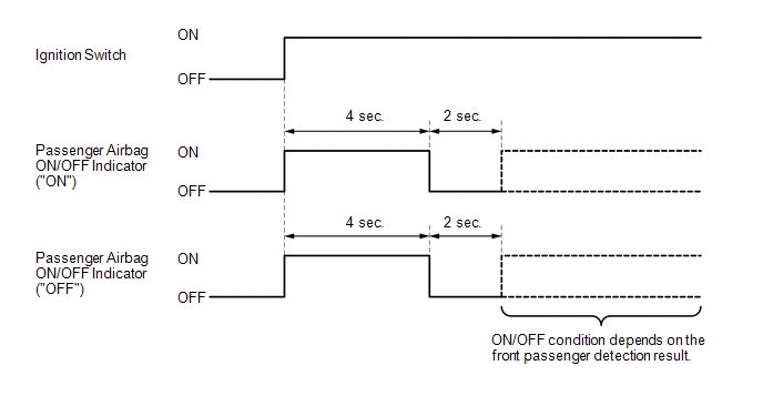
FUNCTION OF PASSENGER AIRBAG ON/OFF INDICATOR
(a) Initial check
(1) Turn the ignition switch ON.
(2) The passenger airbag ON/OFF indicator comes on for approximately 4 seconds, then goes off for approximately 2 seconds.
(3) Approximately 6 seconds after the ignition switch is turned ON, the passenger airbag ON/OFF indicator will indicate ON/OFF depending on the following conditions.
Indicator Operation|
Front Passenger Seat Condition |
Passenger Airbag ON/OFF Indicator |
SRS Warning Light |
|
|---|---|---|---|
|
ON Indicator |
OFF Indicator |
||
|
Vacant |
OFF |
ON |
OFF |
|
Adult*1 is seated |
ON |
OFF |
OFF |
|
Child*2 is seated |
ON or OFF*2 |
OFF or ON*2 |
OFF |
|
Child restraint system is installed |
OFF |
ON |
OFF |
|
Occupant classification system failure |
OFF |
ON |
ON |
- *1: The system judges a person of average adult weight or more as an adult. If a smaller adult sits in the front passenger seat, the system may not recognize them as an adult depending on their physique and posture.
- *2: The system may not recognize a child or a child in a child restraint system as a child depending on factors such as the positioning of the child restraint system or the child's physique or posture.
HINT:
- The passenger airbag ON/OFF indicator illuminates based on the following timing chart in order to check the indicator light circuit.
- When the occupant classification system is malfunctioning, both the SRS warning light and passenger airbag ON/OFF indicator ("OFF") come on. In this case, perform troubleshooting for the airbag system DTCs first.
PASSENGER AIRBAG ON/OFF INDICATOR CHECK
(a) Turn the ignition switch ON.
(b) Check that the passenger airbag ON/OFF indicator ("ON" and "OFF") comes on for approximately 4 seconds, then goes off for approximately 2 seconds.
HINT:
Refer to the indicator operation table in Function of Passenger Airbag ON/OFF Indicator for the passenger airbag ON/OFF indicator operation when the ignition switch is turned ON and approximately 6 seconds elapse.
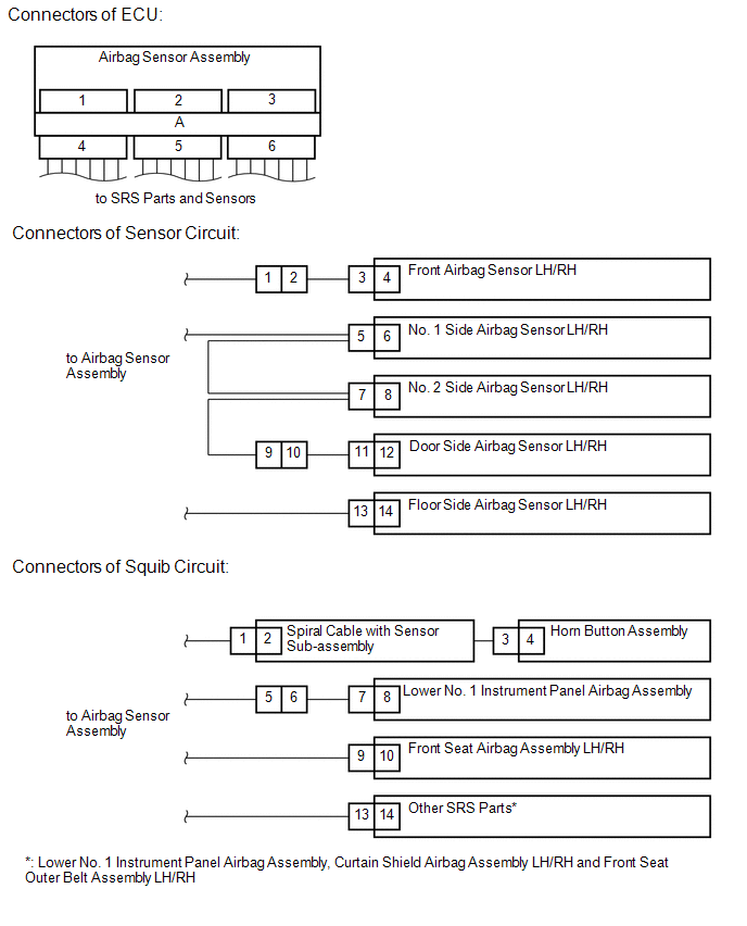
FUNCTION OF SRS CONNECTORS
(a) The SRS connectors are located as shown in the illustration.
|
Connector Type |
Application |
||
|---|---|---|---|
|
ECU |
Sensor Circuit |
Squib Circuit |
|
|
Terminal Twin-lock Mechanism |
Connectors 4, 5, 6 |
Connectors 1, 9, 10 |
Connectors 1, 5, 6 |
|
Half Connection Prevention Mechanism |
- |
- |
Connectors 1, 5, 11 |
|
Activation Prevention Mechanism |
Connectors 4, 5, 6 |
- |
Connectors 2, 4, 6, 8, 10, 12, 14 |
|
Connector Lock Mechanism (1) |
- |
- |
Connectors 3, 7, 13 |
|
Connector Position Assurance Mechanism |
- |
Connectors 2, 3, 5, 7, 11, 13 |
Connectors 9 |
|
Connector Lock Mechanism (2) |
Connector A |
- |
- |
|
Improper Connection Prevention Lock Mechanism |
Connector A |
- |
- |
(b) Terminal twin-lock mechanism
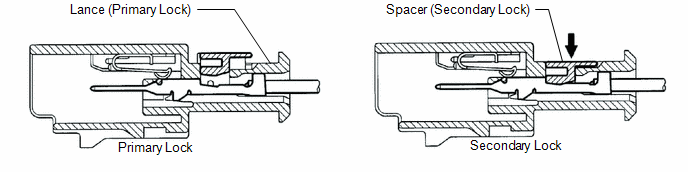
(1) This mechanism is designed to increase the ability of the terminal to remain connected and prevent it from accidentally being disconnected.
(2) The connector has a two-piece construction consisting of the housing and spacer to securely lock the terminal using both the lance (primary lock) and spacer (secondary lock).
(c) Half connection prevention mechanism
(1) This mechanism is designed to prevent the connector from being connected only halfway.
(2) If the connector is not completely connected, the connector is disconnected due to the spring force so that no continuity exists.
(d) Activation prevention mechanism
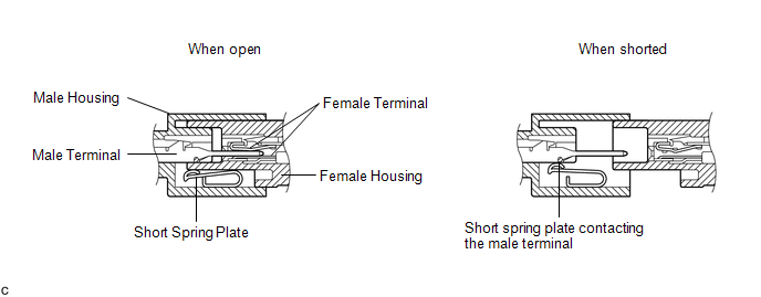
(1) This mechanism is designed to create a short circuit automatically between the positive and negative terminals of an airbag power source connector when disconnected.
(2) The short spring plate contained in the connector creates a closed circuit on the airbag side (no potential difference can occur between both terminals), preventing accidental airbag deployment when servicing.
(e) Connector lock mechanism (1)
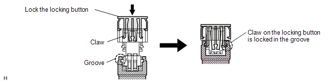
(1) This mechanism is designed to prevent the connector from accidentally being disconnected.
(2) Locking the connector locking button engages the locking button claws in the grooves on the other side of the connector to connect the connector securely.
(f) Connector Position Assurance (CPA) mechanism
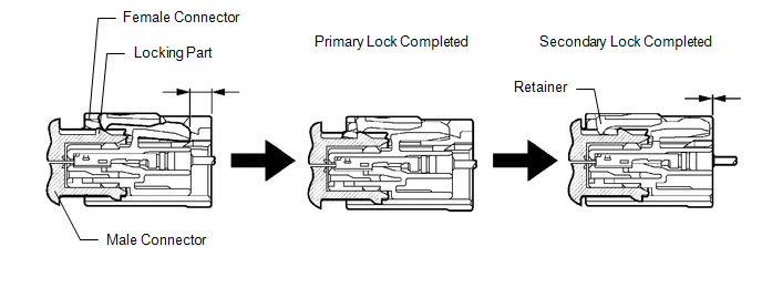
(1) This mechanism is designed to detect when the connector is connected only halfway.
(2) The CPA and female connector slide to the male connector side at the same time and the primary lock is completed when the female connector is engaged with the male connector. From this point, only the CPA slides to the male connector side and secondary lock is completed when the CPA retainer is engaged with the female connector. When the CPA and female connector ends are aligned, they are completely engaged.
(g) Connector lock mechanism (2)
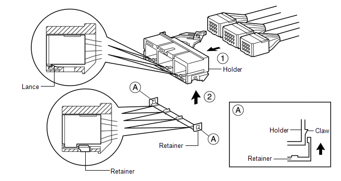
(1) This mechanism is designed to prevent the connector from accidentally being disconnected.
(2) Sliding the connector all the way into the holder and locking the lance completes the primary lock.
(3) Engaging the retainer to the holder as shown in the illustration completes the secondary lock, preventing the connector from accidentally being disconnected.
(h) Improper connection prevention lock mechanism
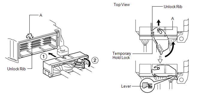
(1) This mechanism is designed to prevent the connector from being connected only halfway.
(2) When the holder is connected to the airbag sensor assembly, the unlock rib unlocks the temporary hold lock, allowing the lever to be pushed in by rotating around axis A.
(3) Locking the lever to the holder locks the holder securely.
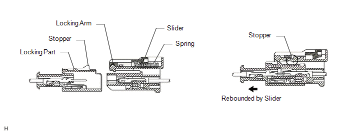
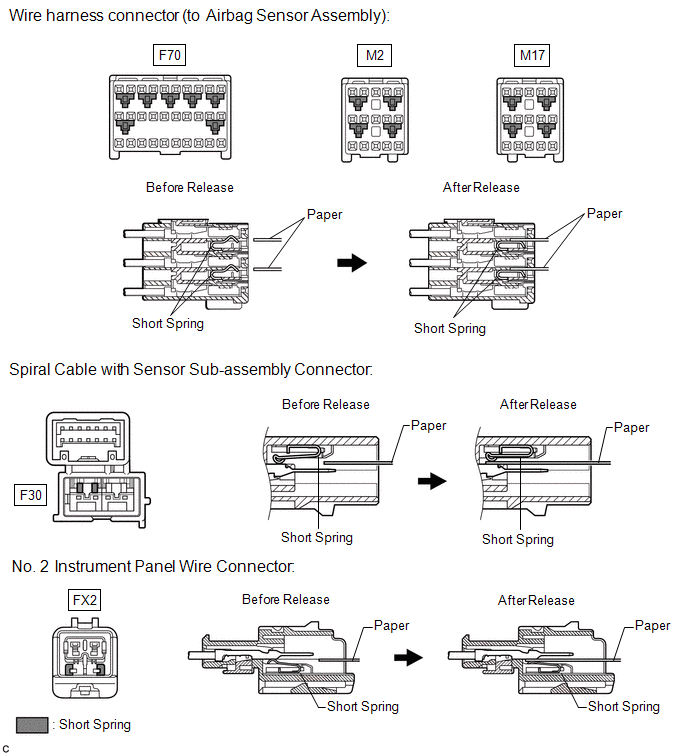
ACTIVATION PREVENTION MECHANISM
(a) Function of activation prevention mechanism
(1) An activation prevention mechanism is built into the connector of the airbag system squib circuit to prevent accidental airbag and pretensioner deployment.
(2) This mechanism closes the circuit when the connector is disconnected by bringing the short spring into contact with the terminals and insulating the circuit from external power sources to prevent accidental airbag and pretensioner deployment.
(b) Releasing of activation prevention mechanism
(1) To release the activation prevention mechanism, insert a piece of paper with the same thickness as the male terminal (approximately 0.5 mm (0.0197 in.)) between the terminals and short spring to break the connection.
(2) Refer to the following illustrations concerning connectors utilizing the activation prevention mechanism and its release method.
CAUTION:
Never release the activation prevention mechanism on the squib connector even when inspecting with the squib disconnected.
NOTICE:
- Do not release the activation prevention mechanism unless specified by the troubleshooting procedure.
- To prevent the terminals and short spring from being damaged, always use a piece of paper with the same thickness as the male terminal.
 Terminals Of Ecu
TERMINALS OF ECU
AIRBAG SENSOR ASSEMBLY (w/o Occupant Classification System)
Terminal No.
Terminal Symbol
Destination
F70-3
P-
...
 Dtc Check / Clear
DTC CHECK / CLEAR
DTC CHECK (USING SST CHECK WIRE)
(a) Check for DTCs (Current DTCs).
(1) Turn the ignition switch ON, and wait for at least 60 seconds.
(2) Using SST, connect terminals TC and C ...
Other materials:
Toyota CH-R Service Manual > Can Communication System: Check Bus 1 Line for Short to +B
DESCRIPTION
There may be a short circuit between one of the CAN bus lines and +B when no
resistance exists between terminal 23 (CA1H) of the central gateway ECU (network
gateway ECU) and terminal 16 (BAT) of the DLC3, or terminal 8 (CA1L) of the central
gateway ECU (network gateway ECU) and t ...
Toyota CH-R Service Manual > Smart Key System(for Entry Function): Back Door Entry Unlock Function does not Operate
DESCRIPTION
If the entry unlock function does not operate for the back door only, but the
entry lock function operates, the request code is being transmitted properly from
the back door. In this case, there may be a problem related to the open switch (connection
between the back door opener s ...
Toyota C-HR (AX20) 2023-2026 Owner's Manual
Toyota CH-R Owners Manual
- For safety and security
- Instrument cluster
- Operation of each component
- Driving
- Interior features
- Maintenance and care
- When trouble arises
- Vehicle specifications
- For owners
Toyota CH-R Service Manual
- Introduction
- Maintenance
- Audio / Video
- Cellular Communication
- Navigation / Multi Info Display
- Park Assist / Monitoring
- Brake (front)
- Brake (rear)
- Brake Control / Dynamic Control Systems
- Brake System (other)
- Parking Brake
- Axle And Differential
- Drive Shaft / Propeller Shaft
- K114 Cvt
- 3zr-fae Battery / Charging
- Networking
- Power Distribution
- Power Assist Systems
- Steering Column
- Steering Gear / Linkage
- Alignment / Handling Diagnosis
- Front Suspension
- Rear Suspension
- Tire / Wheel
- Tire Pressure Monitoring
- Door / Hatch
- Exterior Panels / Trim
- Horn
- Lighting (ext)
- Mirror (ext)
- Window / Glass
- Wiper / Washer
- Door Lock
- Heating / Air Conditioning
- Interior Panels / Trim
- Lighting (int)
- Meter / Gauge / Display
- Mirror (int)
- Power Outlets (int)
- Pre-collision
- Seat
- Seat Belt
- Supplemental Restraint Systems
- Theft Deterrent / Keyless Entry

0.0111