Toyota CH-R Service Manual: System Diagram
SYSTEM DIAGRAM
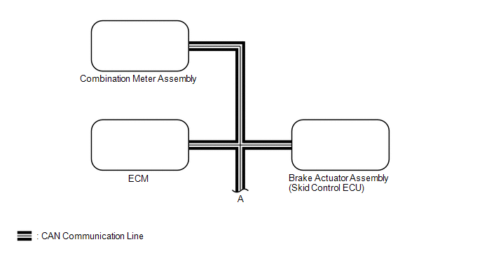
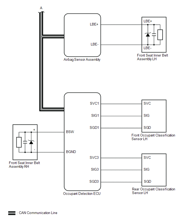
FRONT SEAT BELT WARNING
 Communication Table
|
Sender |
Receiver |
Signal |
Communication Method |
|---|---|---|---|
|
Airbag sensor assembly |
Combination meter assembly |
|
CAN |
|
Brake actuator assembly (Skid control ECU) |
Combination meter assembly |
Vehicle speed |
|
|
ECM |
Combination meter assembly |
Shift position |
|
|
Occupant detection ECU |
Airbag sensor assembly |
|
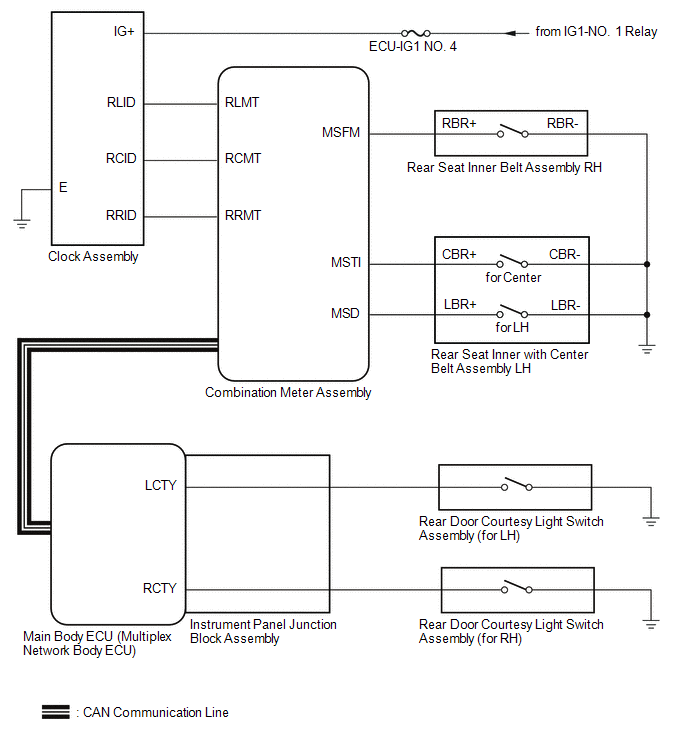
REAR SEAT BELT WARNING
 Communication Table
|
Sender |
Receiver |
Signal |
Communication Method |
|---|---|---|---|
|
Main body ECU (multiplex network body ECU) |
Combination meter assembly |
Rear door courtesy light switch signal (LH/RH) |
CAN |
 System Description
SYSTEM DESCRIPTION
SEAT BELT WARNING SYSTEM DESCRIPTION
(a) Seat belt warning light operation for driver seat belt:
The seat belt warning light on the combination meter assembly blinks or turns
o ...
 How To Proceed With Troubleshooting
CAUTION / NOTICE / HINT
HINT:
Use the following procedure to troubleshoot the seat belt warning system.
*: Use the Techstream.
PROCEDURE
1.
VEHICLE BROU ...
Other materials:
Toyota CH-R Service Manual > Tire Pressure Warning System: Dtc Check / Clear
DTC CHECK / CLEAR
CHECK DTC (for TIRE PRESSURE WARNING ECU AND RECEIVER) (USING Techstream)
(a) Turn the ignition switch off.
(b) Connect the Techstream to the DLC3.
(c) Turn the ignition switch to ON.
(d) Turn the Techstream on.
(e) Enter the following menus: Chassis / Tire Pressure Monitor / ...
Toyota CH-R Service Manual > Meter / Gauge System: System Description
SYSTEM DESCRIPTION
INPUT AND OUTPUT SIGNALS OF COMBINATION METER ASSEMBLY
(a) Meter or Gauge
Item
Condition
Input/Output
Communication line
Signal
Component
Speedometer
Gauge
Input
...
Toyota C-HR (AX20) 2023-2026 Owner's Manual
Toyota CH-R Owners Manual
- For safety and security
- Instrument cluster
- Operation of each component
- Driving
- Interior features
- Maintenance and care
- When trouble arises
- Vehicle specifications
- For owners
Toyota CH-R Service Manual
- Introduction
- Maintenance
- Audio / Video
- Cellular Communication
- Navigation / Multi Info Display
- Park Assist / Monitoring
- Brake (front)
- Brake (rear)
- Brake Control / Dynamic Control Systems
- Brake System (other)
- Parking Brake
- Axle And Differential
- Drive Shaft / Propeller Shaft
- K114 Cvt
- 3zr-fae Battery / Charging
- Networking
- Power Distribution
- Power Assist Systems
- Steering Column
- Steering Gear / Linkage
- Alignment / Handling Diagnosis
- Front Suspension
- Rear Suspension
- Tire / Wheel
- Tire Pressure Monitoring
- Door / Hatch
- Exterior Panels / Trim
- Horn
- Lighting (ext)
- Mirror (ext)
- Window / Glass
- Wiper / Washer
- Door Lock
- Heating / Air Conditioning
- Interior Panels / Trim
- Lighting (int)
- Meter / Gauge / Display
- Mirror (int)
- Power Outlets (int)
- Pre-collision
- Seat
- Seat Belt
- Supplemental Restraint Systems
- Theft Deterrent / Keyless Entry

0.0097