Toyota CH-R Service Manual: Components
COMPONENTS
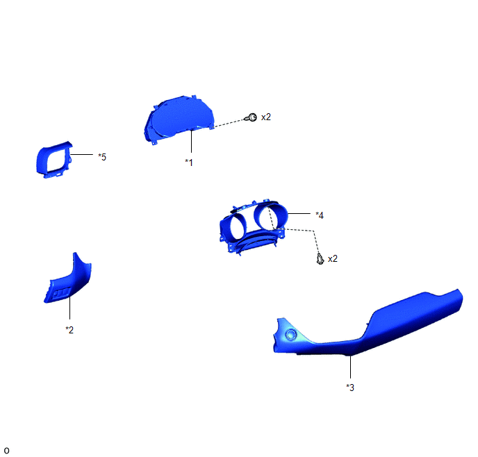
ILLUSTRATION
|
*1 |
COMBINATION METER ASSEMBLY |
*2 |
INSTRUMENT CLUSTER FINISH PANEL ASSEMBLY |
|
*3 |
INSTRUMENT CLUSTER FINISH PANEL GARNISH ASSEMBLY |
*4 |
INSTRUMENT CLUSTER FINISH PANEL SUB-ASSEMBLY |
|
*5 |
NO. 2 INSTRUMENT PANEL GARNISH SUB-ASSEMBLY |
- |
- |
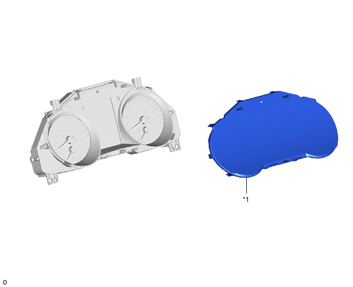
ILLUSTRATION
|
*1 |
COMBINATION METER GLASS |
- |
- |

 Disassembly
DISASSEMBLY
CAUTION / NOTICE / HINT
NOTICE:
When removing and installing the combination meter glass, make sure
not to touch the display panel.
Do not allow any dirt (fingerprints, ...
Other materials:
Toyota CH-R Service Manual > Rear Spoiler: Removal
REMOVAL
PROCEDURE
1. REMOVE BACK DOOR TRIM UPPER PANEL ASSEMBLY
Click here
2. REMOVE NO. 2 BACK DOOR PANEL PROTECTOR
Click here
3. REMOVE NO. 1 BACK DOOR PANEL PROTECTOR
HINT:
Use the same procedure as for the No. 2 back door panel protector side.
4. REMOVE REAR SPOILER ASSEMBLY ...
Toyota CH-R Service Manual > Front Lower Ball Joint: Inspection
INSPECTION
PROCEDURE
1. INSPECT FRONT LOWER BALL JOINT ASSEMBLY
(a) Inspect the turning torque of the ball joint.
(1) Secure the front lower ball joint assembly in a vise using aluminum
plates.
(2) Install the nut to the front lower ball joint assembly stud.
(3) Using a to ...
Toyota C-HR (AX20) 2023-2026 Owner's Manual
Toyota CH-R Owners Manual
- For safety and security
- Instrument cluster
- Operation of each component
- Driving
- Interior features
- Maintenance and care
- When trouble arises
- Vehicle specifications
- For owners
Toyota CH-R Service Manual
- Introduction
- Maintenance
- Audio / Video
- Cellular Communication
- Navigation / Multi Info Display
- Park Assist / Monitoring
- Brake (front)
- Brake (rear)
- Brake Control / Dynamic Control Systems
- Brake System (other)
- Parking Brake
- Axle And Differential
- Drive Shaft / Propeller Shaft
- K114 Cvt
- 3zr-fae Battery / Charging
- Networking
- Power Distribution
- Power Assist Systems
- Steering Column
- Steering Gear / Linkage
- Alignment / Handling Diagnosis
- Front Suspension
- Rear Suspension
- Tire / Wheel
- Tire Pressure Monitoring
- Door / Hatch
- Exterior Panels / Trim
- Horn
- Lighting (ext)
- Mirror (ext)
- Window / Glass
- Wiper / Washer
- Door Lock
- Heating / Air Conditioning
- Interior Panels / Trim
- Lighting (int)
- Meter / Gauge / Display
- Mirror (int)
- Power Outlets (int)
- Pre-collision
- Seat
- Seat Belt
- Supplemental Restraint Systems
- Theft Deterrent / Keyless Entry

0.0074