Toyota CH-R Service Manual: Disassembly
DISASSEMBLY
PROCEDURE
1. PRECAUTION
NOTICE:
Make sure to perform initialization after replacing the No. 1 blower damper servo sub-assembly. If initialization is not performed, the air conditioner unit assembly will not perform properly as the air conditioning amplifier assembly will not be able to recognize the position of the No. 1 blower damper servo sub-assembly.
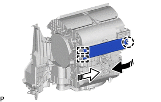
2. REMOVE AIR FILTER COVER PLATE
(a) Disengage the claw and guides as shown in the illustration to remove the air filter cover plate.
.png) |
Remove in this Direction (1) |
.png) |
Remove in this Direction (2) |
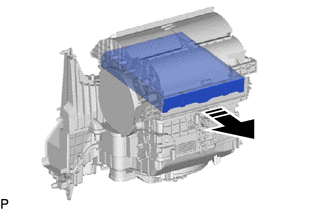
3. REMOVE CLEAN AIR FILTER
(a) Remove the air filter sub-assembly as shown in the illustration.
|
|
Remove in this Direction |
|
(b) Disengage the guides to remove the clean air filter from the cooling unit parts. |
|
.png)
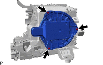
4. REMOVE BLOWER MOTOR WITH FAN SUB-ASSEMBLY
|
(a) Remove the 3 screws and the blower motor with fan sub-assembly. |
|
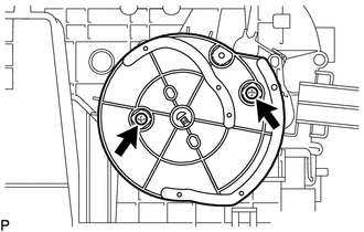
5. REMOVE NO. 1 BLOWER DAMPER SERVO SUB-ASSEMBLY
|
(a) Remove the 2 screws and the No. 1 blower damper servo sub-assembly. |
|
 Components
COMPONENTS
ILLUSTRATION
*1
BLOWER ASSEMBLY
*2
NO. 2 AIR DUCT
●
Non-reusable part
-
-
ILLUS ...
 Removal
REMOVAL
CAUTION / NOTICE / HINT
The necessary procedures (adjustment, calibration, initialization or registration)
that must be performed after parts are removed and installed, or replaced during ...
Other materials:
Toyota CH-R Service Manual > Smart Key System(for Entry Function): Data List / Active Test
DATA LIST / ACTIVE TEST
DATA LIST
NOTICE:
In the table below, the values listed under "Normal Condition" are reference
values. Do not depend solely on these reference values when deciding whether
a part is faulty or not.
When using the Techstream with the engine swit ...
Toyota CH-R Service Manual > Immobiliser System(w/o Smart Key System): Precaution
PRECAUTION
PRECAUTIONS WHEN USING TECHSTREAM
(a) After all DTCs are cleared, check if the malfunction occurs again 6 seconds
after turning the ignition switch ON.
PRECAUTIONS FOR THE KEY
(a) The key is a precision instrument. Be sure to observe the following:
(1) Do not drop or strike the key ...
Toyota C-HR (AX20) 2023-2026 Owner's Manual
Toyota CH-R Owners Manual
- For safety and security
- Instrument cluster
- Operation of each component
- Driving
- Interior features
- Maintenance and care
- When trouble arises
- Vehicle specifications
- For owners
Toyota CH-R Service Manual
- Introduction
- Maintenance
- Audio / Video
- Cellular Communication
- Navigation / Multi Info Display
- Park Assist / Monitoring
- Brake (front)
- Brake (rear)
- Brake Control / Dynamic Control Systems
- Brake System (other)
- Parking Brake
- Axle And Differential
- Drive Shaft / Propeller Shaft
- K114 Cvt
- 3zr-fae Battery / Charging
- Networking
- Power Distribution
- Power Assist Systems
- Steering Column
- Steering Gear / Linkage
- Alignment / Handling Diagnosis
- Front Suspension
- Rear Suspension
- Tire / Wheel
- Tire Pressure Monitoring
- Door / Hatch
- Exterior Panels / Trim
- Horn
- Lighting (ext)
- Mirror (ext)
- Window / Glass
- Wiper / Washer
- Door Lock
- Heating / Air Conditioning
- Interior Panels / Trim
- Lighting (int)
- Meter / Gauge / Display
- Mirror (int)
- Power Outlets (int)
- Pre-collision
- Seat
- Seat Belt
- Supplemental Restraint Systems
- Theft Deterrent / Keyless Entry

0.0084