Toyota CH-R Service Manual: Components
COMPONENTS
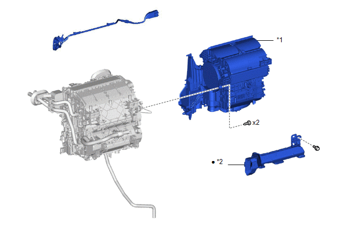
ILLUSTRATION
|
*1 |
BLOWER ASSEMBLY |
*2 |
NO. 2 AIR DUCT |
|
● |
Non-reusable part |
- |
- |
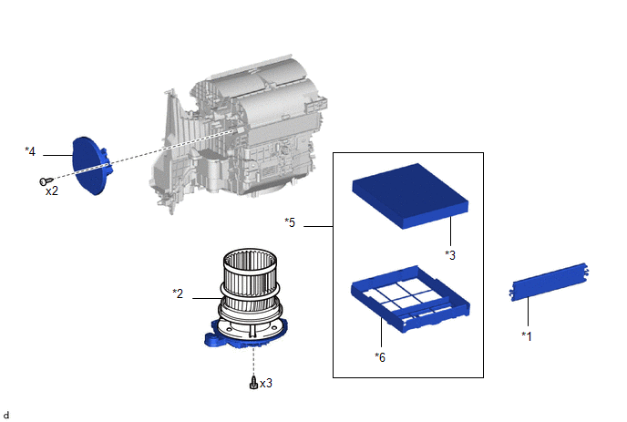
ILLUSTRATION
|
*1 |
AIR FILTER COVER PLATE |
*2 |
BLOWER MOTOR WITH FAN SUB-ASSEMBLY |
|
*3 |
CLEAN AIR FILTER |
*4 |
NO. 1 BLOWER DAMPER SERVO SUB-ASSEMBLY |
|
*5 |
AIR FILTER COVER PLATE |
*6 |
COOLING UNIT PARTS |

 Disassembly
DISASSEMBLY
PROCEDURE
1. PRECAUTION
NOTICE:
Make sure to perform initialization after replacing the No. 1 blower damper servo
sub-assembly. If initialization is not performed, the air conditione ...
Other materials:
Toyota CH-R Owners Manual > Adjusting the steering wheel and mirrors: Steering wheel
Adjustment procedure
1. Hold the steering wheel and push the lever down.
2. Adjust to the ideal position by moving the steering wheel horizontally and
vertically.
After adjustment, pull the lever up to secure the steering wheel.
Horn
To sound the horn, press on or close to the
mark.
...
Toyota CH-R Service Manual > Washer Motor: Components
COMPONENTS
ILLUSTRATION
*1
FRONT FENDER LINER RH
*2
FRONT WHEEL OPENING EXTENSION PAD RH
*3
WINDSHIELD WASHER MOTOR AND PUMP ASSEMBLY
-
-
...
Toyota C-HR (AX20) 2023-2026 Owner's Manual
Toyota CH-R Owners Manual
- For safety and security
- Instrument cluster
- Operation of each component
- Driving
- Interior features
- Maintenance and care
- When trouble arises
- Vehicle specifications
- For owners
Toyota CH-R Service Manual
- Introduction
- Maintenance
- Audio / Video
- Cellular Communication
- Navigation / Multi Info Display
- Park Assist / Monitoring
- Brake (front)
- Brake (rear)
- Brake Control / Dynamic Control Systems
- Brake System (other)
- Parking Brake
- Axle And Differential
- Drive Shaft / Propeller Shaft
- K114 Cvt
- 3zr-fae Battery / Charging
- Networking
- Power Distribution
- Power Assist Systems
- Steering Column
- Steering Gear / Linkage
- Alignment / Handling Diagnosis
- Front Suspension
- Rear Suspension
- Tire / Wheel
- Tire Pressure Monitoring
- Door / Hatch
- Exterior Panels / Trim
- Horn
- Lighting (ext)
- Mirror (ext)
- Window / Glass
- Wiper / Washer
- Door Lock
- Heating / Air Conditioning
- Interior Panels / Trim
- Lighting (int)
- Meter / Gauge / Display
- Mirror (int)
- Power Outlets (int)
- Pre-collision
- Seat
- Seat Belt
- Supplemental Restraint Systems
- Theft Deterrent / Keyless Entry

0.0086