Toyota CH-R Service Manual: General Information
GENERAL INFORMATION
- A large number of ECU controlled systems are used in this vehicle. In general, ECU controlled systems are considered to be very intricate, requiring a high level of technical knowledge to troubleshoot. However, most problem checking procedures only involve inspecting the ECU controlled system circuits one by one. An adequate understanding of the system and a basic knowledge of electricity is enough to perform effective troubleshooting, accurate diagnosis and necessary repairs.
- (For using the Techstream*)
HINT:
*: The Techstream is the name for the diagnostic tester in North America.
- Before using the Techstream, read the operator's manual thoroughly.
- If the Techstream cannot communicate with the ECU controlled
systems when connected to the DLC3 with the ignition switch ON and
the Techstream on, there is a problem on the vehicle side or the
Techstream side.
- If communication is possible when the Techstream is connected to another vehicle, inspect the diagnosis data link line (bus (+) line), CANH and CANL lines, and the power circuits for the vehicle ECUs.
- If communication is still not possible when the Techstream is connected to another vehicle, the problem is probably in the Techstream itself. Perform the Self Test procedure outlined in the Techstream operator's manual.
TROUBLESHOOTING PROCEDURES
- The troubleshooting procedures consist of diagnosis procedures for when
a DTC is stored and diagnosis procedures for when no DTC is stored. The
basic idea is explained in the following table.
Procedure Type
Details
Troubleshooting Method
DTC Based Diagnosis
The diagnosis procedure is based on the DTC that is stored.
The malfunctioning part is identified based on the DTC detection conditions using a process of elimination.
The possible trouble areas are eliminated one-by-one using the Techstream and inspection of related parts.
Symptom Based Diagnosis
(No DTCs stored)
The diagnosis procedure is based on problem symptoms.
The malfunctioning part is identified based on the problem symptoms using a process of elimination.
The possible trouble areas are eliminated one-by-one using the Techstream and inspection of related parts.
- Vehicle systems are complex and use many ECUs that are difficult to inspect independently. Therefore, a process of elimination is used, where components that can be inspected individually are inspected, and if no problems are found in these components, the related ECU is identified as the problem and replaced.
- It is extremely important to ask the customer about the environment and the conditions present when the problem occurred (Customer Problem Analysis). This makes it possible to simulate the conditions and confirm the symptom. If the symptom cannot be confirmed or the DTC does not recur, the malfunctioning part may not be identified using the troubleshooting procedure, and the ECU for the related system may be replaced even though it is not defective. If this happens, the original problem will not be solved.
- In order to prevent endless expansion of troubleshooting procedures, the troubleshooting procedures are written with the assumption that multiple malfunctions do not occur simultaneously for a single problem symptom.
- To identify the malfunctioning part, troubleshooting procedures narrow down the target by separating components, ECUs and wire harnesses during the inspection. If the wire harness is identified as the cause of the problem, it is necessary to inspect not only the connections to components and ECUs but also all of the wire harness connectors between the component and the ECU.
DESCRIPTION
(a) The data of each system and Diagnostic Trouble Codes (DTCs) can be read from the Data Link Connector 3 (DLC3) of the vehicle. When the system seems to be malfunctioning, use the Techstream to check for malfunctions and perform repairs.
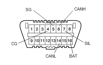
CHECK DLC3
(a) The vehicle ECUs use ISO 15765-4 communication protocol. The terminal arrangement of the DLC3 complies with SAE J1962 and matches the ISO 15765-4 format.
|
Symbol |
Terminal No. |
Name |
Reference Terminal |
Result |
Condition |
|---|---|---|---|---|---|
|
SIL |
7 |
Bus "+" line |
5 - Signal ground |
Pulse generation |
During transmission |
|
CG |
4 |
Chassis ground |
Body ground |
1 Ω or less |
Always |
|
SG |
5 |
Signal ground |
Body ground |
1 Ω or less |
Always |
|
BAT |
16 |
Battery positive |
Body ground |
11 to 14 V |
Always |
|
CANH |
6 |
CAN "High" line |
14 - CANL |
54 to 69 Ω |
Ignition switch off* |
|
Battery positive |
6 kΩ or higher |
Ignition switch off* |
|||
|
4 - CG |
200 Ω or higher |
Ignition switch off* |
|||
|
CANL |
14 |
CAN "Low" line |
Battery positive |
6 kΩ or higher |
Ignition switch off* |
|
4 - CG |
200 Ω or higher |
Ignition switch off* |
NOTICE:
*: Before measuring the resistance, leave the vehicle as is for at least 1 minute and do not operate the ignition switch, any other switches or the doors.
If the result is not as specified, the DLC3 may be malfunctioning. Repair or replace the harness or connector.

 Electronic Circuit Inspection Procedure
ELECTRONIC CIRCUIT INSPECTION PROCEDURE
BASIC INSPECTION
(a) WHEN MEASURING RESISTANCE OF ELECTRONIC PARTS
(1) Unless otherwise stated, all resistance measurements are standard values
measured at ...
Other materials:
Toyota CH-R Service Manual > Automatic Light Control Sensor: Installation
INSTALLATION
PROCEDURE
1. INSTALL AUTOMATIC LIGHT CONTROL SENSOR
(a) Engage the claws to install the automatic light control sensor.
(b) Connect the connector.
2. INSTALL DEFROSTER NOZZLE ASSEMBLY
Click here
3. INSTALL INSTRUM ...
Toyota CH-R Service Manual > Rear Shock Absorber: Disposal
DISPOSAL
PROCEDURE
1. DISPOSE OF REAR SHOCK ABSORBER ASSEMBLY
(a) Extend the piston rod and secure the rear shock absorber assembly
at an angle in a vise.
(b) Using a hacksaw, slowly make a hole at the position indicated by the arrow ...
Toyota C-HR (AX20) 2023-2026 Owner's Manual
Toyota CH-R Owners Manual
- For safety and security
- Instrument cluster
- Operation of each component
- Driving
- Interior features
- Maintenance and care
- When trouble arises
- Vehicle specifications
- For owners
Toyota CH-R Service Manual
- Introduction
- Maintenance
- Audio / Video
- Cellular Communication
- Navigation / Multi Info Display
- Park Assist / Monitoring
- Brake (front)
- Brake (rear)
- Brake Control / Dynamic Control Systems
- Brake System (other)
- Parking Brake
- Axle And Differential
- Drive Shaft / Propeller Shaft
- K114 Cvt
- 3zr-fae Battery / Charging
- Networking
- Power Distribution
- Power Assist Systems
- Steering Column
- Steering Gear / Linkage
- Alignment / Handling Diagnosis
- Front Suspension
- Rear Suspension
- Tire / Wheel
- Tire Pressure Monitoring
- Door / Hatch
- Exterior Panels / Trim
- Horn
- Lighting (ext)
- Mirror (ext)
- Window / Glass
- Wiper / Washer
- Door Lock
- Heating / Air Conditioning
- Interior Panels / Trim
- Lighting (int)
- Meter / Gauge / Display
- Mirror (int)
- Power Outlets (int)
- Pre-collision
- Seat
- Seat Belt
- Supplemental Restraint Systems
- Theft Deterrent / Keyless Entry

0.0083