Toyota CH-R Service Manual: Components
COMPONENTS
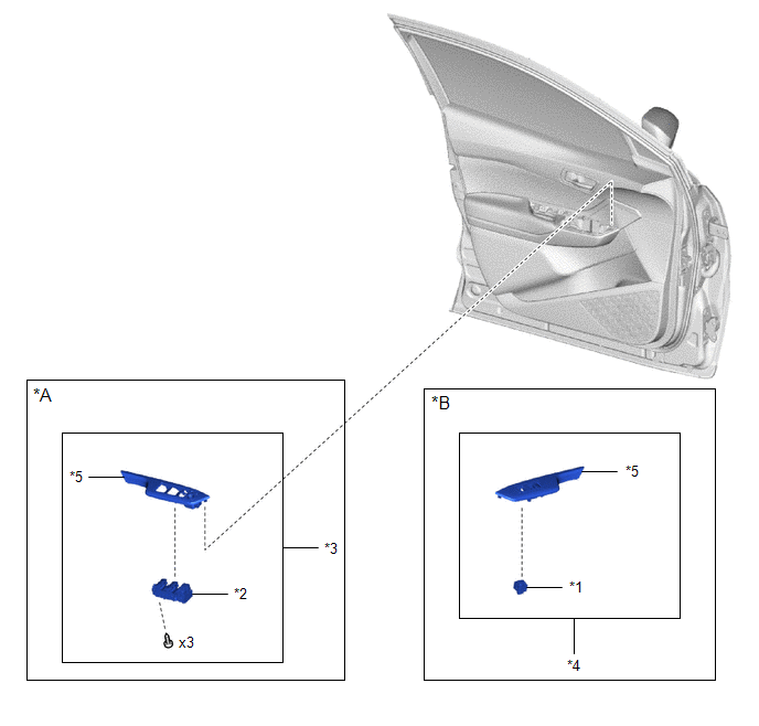
ILLUSTRATION
|
*A |
for Driver Side |
*B |
for Front Passenger Side |
|
*1 |
DOOR CONTROL SWITCH ASSEMBLY |
*2 |
MULTIPLEX NETWORK MASTER SWITCH ASSEMBLY |
|
*3 |
MULTIPLEX NETWORK MASTER SWITCH ASSEMBLY WITH FRONT ARMREST BASE UPPER PANEL |
*4 |
POWER WINDOW REGULATOR SWITCH ASSEMBLY WITH FRONT ARMREST BASE UPPER PANEL |
|
*5 |
FRONT ARMREST BASE UPPER PANEL |
- |
- |

 Inspection
INSPECTION
PROCEDURE
1. INSPECT MULTIPLEX NETWORK MASTER SWITCH ASSEMBLY
(a) Check that the LED illuminates.
(1) Apply battery voltage to the multiplex network master switch assembly
...
Other materials:
Toyota CH-R Service Manual > Blind Spot Monitor System: Software Incompatibility with Body Control Module "B" (U1331)
DESCRIPTION
This DTC is stored when the destination information of the main body ECU (multiplex
network body ECU) does not match that of the blind spot monitor sensors.
DTC No.
Detection Item
DTC Detection Condition
Trouble Area
U1331
...
Toyota CH-R Service Manual > Power Steering System: Calibration
CALIBRATION
TORQUE SENSOR ZERO POINT CALIBRATION (USING TECHSTREAM)
NOTICE:
Perform torque sensor zero point calibration if any of the following conditions
occur:
The power steering ECU assembly has been replaced.
The electric power steering column sub-assembly has been replaced.
...
Toyota C-HR (AX20) 2023-2026 Owner's Manual
Toyota CH-R Owners Manual
- For safety and security
- Instrument cluster
- Operation of each component
- Driving
- Interior features
- Maintenance and care
- When trouble arises
- Vehicle specifications
- For owners
Toyota CH-R Service Manual
- Introduction
- Maintenance
- Audio / Video
- Cellular Communication
- Navigation / Multi Info Display
- Park Assist / Monitoring
- Brake (front)
- Brake (rear)
- Brake Control / Dynamic Control Systems
- Brake System (other)
- Parking Brake
- Axle And Differential
- Drive Shaft / Propeller Shaft
- K114 Cvt
- 3zr-fae Battery / Charging
- Networking
- Power Distribution
- Power Assist Systems
- Steering Column
- Steering Gear / Linkage
- Alignment / Handling Diagnosis
- Front Suspension
- Rear Suspension
- Tire / Wheel
- Tire Pressure Monitoring
- Door / Hatch
- Exterior Panels / Trim
- Horn
- Lighting (ext)
- Mirror (ext)
- Window / Glass
- Wiper / Washer
- Door Lock
- Heating / Air Conditioning
- Interior Panels / Trim
- Lighting (int)
- Meter / Gauge / Display
- Mirror (int)
- Power Outlets (int)
- Pre-collision
- Seat
- Seat Belt
- Supplemental Restraint Systems
- Theft Deterrent / Keyless Entry

0.0068