Toyota CH-R Service Manual: Removal
REMOVAL
CAUTION / NOTICE / HINT
The necessary procedures (adjustment, calibration, initialization or registration) that must be performed after parts are removed and installed, or replaced during windshield glass removal/installation are shown below.
Necessary Procedures After Parts Removed/Installed/Replaced|
Replaced Part or Performed Procedure |
Necessary Procedure |
Effects / Inoperative when not performed |
Link |
|---|---|---|---|
|
Windshield glass |
Adjust forward recognition camera |
|
|
NOTICE:
When replacing the windshield glass of a vehicle equipped with a forward recognition camera, make sure to use a Toyota genuine part. If a non-Toyota genuine part is used, the forward recognition camera may not be able to be installed due to a missing bracket. Also, the dynamic radar cruise control system, lane departure alert system, pre-crash safety system, forward recognition camera system or automatic high beam system may not operate properly due to a difference in the transmissivity or black ceramic border.
PROCEDURE
1. REMOVE WINDSHIELD OUTSIDE MOULDING LH
Click here
.gif)
2. REMOVE WINDSHIELD OUTSIDE MOULDING RH
HINT:
Use the same procedure as for the LH side.
3. REMOVE FRONT WIPER ARM HEAD CAP
Click here
4. REMOVE FRONT WIPER ARM AND BLADE ASSEMBLY LH
Click here
5. REMOVE FRONT WIPER ARM AND BLADE ASSEMBLY RH
Click here
6. REMOVE COWL TOP VENTILATOR LOUVER SUB-ASSEMBLY
Click here
7. REMOVE INNER REAR VIEW MIRROR ASSEMBLY
Click here
8. REMOVE RAIN SENSOR (w/ Rain Sensor)
Click here
9. REMOVE FORWARD RECOGNITION CAMERA (w/ Toyota Safety Sense P)
Click here
10. REMOVE MAP LIGHT ASSEMBLY
Click here
11. REMOVE VANITY LIGHT ASSEMBLY
Click here
12. DISCONNECT FRONT DOOR OPENING TRIM WEATHERSTRIP LH
Click here
13. DISCONNECT FRONT DOOR OPENING TRIM WEATHERSTRIP RH
HINT:
Use the same procedure as for the LH side.
14. REMOVE FRONT PILLAR GARNISH LH
Click here
15. REMOVE FRONT PILLAR GARNISH RH
HINT:
Use the same procedure as for the LH side.
16. REMOVE ASSIST GRIP COVER
Click here
17. REMOVE ASSIST GRIP SUB-ASSEMBLY
Click here
18. REMOVE VISOR BRACKET COVER
Click here
19. REMOVE VISOR ASSEMBLY LH (w/ Vanity Light)
Click here
20. REMOVE VISOR ASSEMBLY RH (w/ Vanity Light)
HINT:
Use the same procedure as for the LH side.
21. REMOVE VISOR ASSEMBLY LH (w/o Vanity Light)
Click here
22. REMOVE VISOR ASSEMBLY RH (w/o Vanity Light)
HINT:
Use the same procedure as for the LH side.
23. REMOVE VISOR HOLDER
Click here
24. SEPARATE ROOF HEADLINING
(a) Slightly lower the front section of the roof headlining so that the windshield glass can be removed.
NOTICE:
Do not damage the roof headlining or vehicle interior.
HINT:
It is not necessary to completely remove the roof headlining.
25. REMOVE WINDSHIELD GLASS
(a) w/ Windshield Deicer System :
(1) Disconnect the connector of the windshield deicer.
(b) Apply protective tape to the area around the installation position of the windshield glass on the vehicle body to prevent it from being scratched.
.png) |
Protective Tape |
|
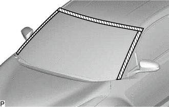
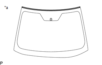
(c) Using a knife, cut off the windshield outside moulding as shown in the illustration. |
|
|
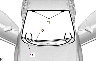
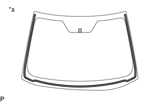
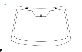
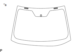
(d) Place matchmarks on the windshield glass and vehicle body at the locations indicated in the illustration. HINT: Matchmarks are not necessary if the windshield glass is not going to be reused. |
|
|
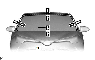
(e) Pass a piano wire between the vehicle body and windshield glass from the interior. |
|
(f) Tie both wire ends to wooden blocks or similar objects that can serve as handles.
(g) Cut the adhesive by pulling the piano wire around the windshield glass.
NOTICE:
- When separating the windshield glass, be careful not to damage the paint or interior and exterior ornaments.
- To prevent the instrument panel safety pad sub-assembly from being scratched when removing the windshield glass, place a plastic sheet between the piano wire and instrument panel safety pad sub-assembly.
- Do not damage the front window inner center moulding.
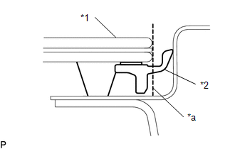
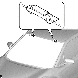
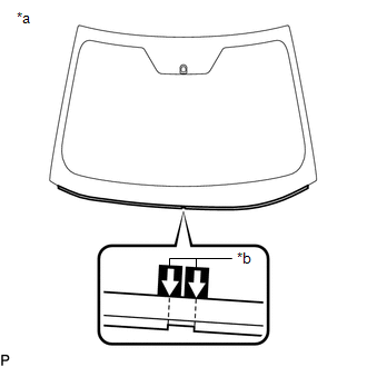
(h) Disengage the windshield glass stoppers.
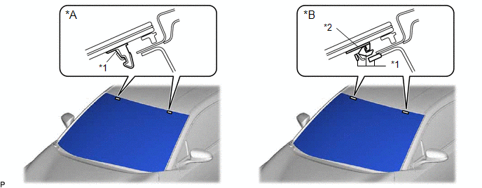
|
*A |
for 1-piece Type |
*B |
for 2-piece Type |
|
*1 |
No. 1 Windshield Glass Stopper |
*2 |
No. 2 Windshield Glass Stopper |
NOTICE:
- The No. 1 windshield glass stoppers and No. 2 windshield glass stoppers are installed to the windshield glass as shown in the illustration. Be careful not to damage the windshield glass when cutting the adhesive.
- To prevent the windshield glass from falling when performing this operation, be sure to hold the windshield glass using suction cups.
HINT:
Depending on the vehicle, either 1-piece type or 2-piece type stoppers may be present.
(i) Using suction cups, remove the windshield glass.
NOTICE:
- Be careful not to drop the windshield glass.
- Leave as much adhesive on the vehicle body as possible when removing the windshield glass.
26. REMOVE WINDOW GLASS ADHESIVE DAM
(a) When reusing the windshield glass:
|
(1) Using a scraper, remove the window glass adhesive dam. NOTICE:
|
|
27. REMOVE WINDSHIELD OUTSIDE MOULDING
(a) When reusing the windshield glass:
|
(1) Using a scraper, remove the windshield outside moulding. NOTICE:
|
|
28. REMOVE NO. 1 WINDSHIELD GLASS STOPPER (for 1-piece Type)
(a) When reusing the windshield glass:
|
(1) Using a scraper, remove the 2 No. 1 windshield glass stoppers. NOTICE:
|
|
29. REMOVE NO. 2 WINDSHIELD GLASS STOPPER (for 2-piece Type)
(a) When reusing the windshield glass:
|
(1) Using a scraper, remove the 2 No. 2 windshield glass stoppers. NOTICE:
|
|
30. REMOVE NO. 1 WINDSHIELD GLASS STOPPER (for 2-piece Type)
|
(a) Remove the 2 No. 1 windshield glass stoppers from the vehicle body. NOTICE: Be sure to replace the No. 1 windshield glass stoppers with new ones. |
|
31. REMOVE FRONT WINDOW INNER CENTER MOULDING
HINT:
Perform the following procedure only when replacement of a front window inner center moulding is necessary.
|
(a) Place matchmarks on the windshield glass at the locations indicated in the illustration. |
|
(b) Using a scraper, remove the front window inner center moulding.
NOTICE:
- Be careful not to damage the windshield glass.
- Be sure to replace the front window inner center moulding with a new one.
 Components
COMPONENTS
ILLUSTRATION
*1
COWL TOP VENTILATOR LOUVER SUB-ASSEMBLY
*2
FRONT WIPER ARM AND BLADE ASSEMBLY LH
*3
FRONT WIPER A ...
 Installation
INSTALLATION
CAUTION / NOTICE / HINT
NOTICE:
When replacing the windshield glass of a vehicle equipped with a forward recognition
camera, make sure to use a Toyota genuine part. If a non-Toyota g ...
Other materials:
Toyota CH-R Service Manual > Steering Pad: On-vehicle Inspection
ON-VEHICLE INSPECTION
CAUTION / NOTICE / HINT
CAUTION:
Be sure to correctly follow the removal and installation procedures for the horn
button assembly.
PROCEDURE
1. INSPECT HORN BUTTON ASSEMBLY (for Vehicle not Involved in Collision)
(a) Perform a diagnostic system check.
Click here
(b) ...
Toyota CH-R Service Manual > Lin Communication System: System Description
SYSTEM DESCRIPTION
LIN COMMUNICATION SYSTEM DESCRIPTION
The LIN communication system is used for communication between the components
in the tables below. If communication cannot be performed through LIN communication
such as when there is an open or short in a communication line, the master c ...
Toyota C-HR (AX20) 2023-2026 Owner's Manual
Toyota CH-R Owners Manual
- For safety and security
- Instrument cluster
- Operation of each component
- Driving
- Interior features
- Maintenance and care
- When trouble arises
- Vehicle specifications
- For owners
Toyota CH-R Service Manual
- Introduction
- Maintenance
- Audio / Video
- Cellular Communication
- Navigation / Multi Info Display
- Park Assist / Monitoring
- Brake (front)
- Brake (rear)
- Brake Control / Dynamic Control Systems
- Brake System (other)
- Parking Brake
- Axle And Differential
- Drive Shaft / Propeller Shaft
- K114 Cvt
- 3zr-fae Battery / Charging
- Networking
- Power Distribution
- Power Assist Systems
- Steering Column
- Steering Gear / Linkage
- Alignment / Handling Diagnosis
- Front Suspension
- Rear Suspension
- Tire / Wheel
- Tire Pressure Monitoring
- Door / Hatch
- Exterior Panels / Trim
- Horn
- Lighting (ext)
- Mirror (ext)
- Window / Glass
- Wiper / Washer
- Door Lock
- Heating / Air Conditioning
- Interior Panels / Trim
- Lighting (int)
- Meter / Gauge / Display
- Mirror (int)
- Power Outlets (int)
- Pre-collision
- Seat
- Seat Belt
- Supplemental Restraint Systems
- Theft Deterrent / Keyless Entry

0.0088