Toyota CH-R Service Manual: Parts Location
PARTS LOCATION
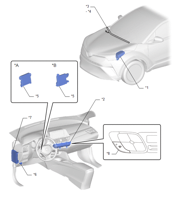
ILLUSTRATION
|
*A |
for TMMT Made |
*B |
for TMC Made |
|
*1 |
NO. 1 ENGINE ROOM RELAY BLOCK - DEICER FUSE |
*2 |
AIR CONDITIONING CONTROL ASSEMBLY |
|
*3 |
WINDSHIELD GLASS |
*4 |
WINDSHIELD DEICER |
|
*5 |
AIR CONDITIONING AMPLIFIER ASSEMBLY |
*6 |
DLC3 |
|
*7 |
INSTRUMENT PANEL JUNCTION BLOCK - DEICER RELAY - ECU-IG1 NO. 4 FUSE - ECU-B NO. 2 FUSE |
*8 |
WINDSHIELD DEICER SWITCH |
 Precaution
PRECAUTION
IGNITION SWITCH EXPRESSIONS
(a) The type of ignition switch used on this model differs according to the specifications
of the vehicle. The expressions listed in the table below are used ...
 System Diagram
SYSTEM DIAGRAM
...
Other materials:
Toyota CH-R Service Manual > Pre-collision System: System Diagram
SYSTEM DIAGRAM
Communication Table
Sender
Receiver
Signal
Line
Millimeter Wave Radar Sensor Assembly
Skid Control ECU (Brake Actuator Assembly)
Brake assist standby signal
Pre-collision brake ope ...
Toyota CH-R Owners Manual > Driving procedures: Parking brake
A selections can be made as desired from the following modes.
Automatic mode
The parking brake is set or released automatically according to shift lever operation.
Even when in automatic mode, the parking brake can be set and released manually.
Turns automatic mode on (while the vehicle is ...
Toyota C-HR (AX20) 2023-2026 Owner's Manual
Toyota CH-R Owners Manual
- For safety and security
- Instrument cluster
- Operation of each component
- Driving
- Interior features
- Maintenance and care
- When trouble arises
- Vehicle specifications
- For owners
Toyota CH-R Service Manual
- Introduction
- Maintenance
- Audio / Video
- Cellular Communication
- Navigation / Multi Info Display
- Park Assist / Monitoring
- Brake (front)
- Brake (rear)
- Brake Control / Dynamic Control Systems
- Brake System (other)
- Parking Brake
- Axle And Differential
- Drive Shaft / Propeller Shaft
- K114 Cvt
- 3zr-fae Battery / Charging
- Networking
- Power Distribution
- Power Assist Systems
- Steering Column
- Steering Gear / Linkage
- Alignment / Handling Diagnosis
- Front Suspension
- Rear Suspension
- Tire / Wheel
- Tire Pressure Monitoring
- Door / Hatch
- Exterior Panels / Trim
- Horn
- Lighting (ext)
- Mirror (ext)
- Window / Glass
- Wiper / Washer
- Door Lock
- Heating / Air Conditioning
- Interior Panels / Trim
- Lighting (int)
- Meter / Gauge / Display
- Mirror (int)
- Power Outlets (int)
- Pre-collision
- Seat
- Seat Belt
- Supplemental Restraint Systems
- Theft Deterrent / Keyless Entry

0.0081