Toyota CH-R Service Manual: Window Defogger Wire
Precaution
PRECAUTION
IGNITION SWITCH EXPRESSIONS
(a) The type of ignition switch used on this model differs depending on the specifications of the vehicle. The expressions listed in the table below are used in this section.
|
Expression |
Ignition Switch (Position) |
Engine Switch (Condition) |
|---|---|---|
|
Ignition Switch off |
LOCK |
Off (Lock) |
|
Ignition Switch ACC |
ACC |
On (ACC) |
|
Ignition Switch ON |
ON |
On (IG) |
|
Engine Start |
START |
On (Start) |
On-vehicle Inspection
ON-VEHICLE INSPECTION
PROCEDURE
1. INSPECT BACK DOOR GLASS (DEFOGGER WIRE)
NOTICE:
- When cleaning the glass, wipe the glass along the wire using a soft, dry cloth. Take care not to damage the defogger wires.
- Do not use detergents or glass cleaners that have abrasive ingredients.
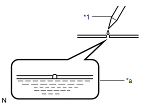
- When measuring voltage, wrap a piece of tin foil around the tip of the negative (-) tester probe and press the foil against the wire with your finger as shown in the illustration.
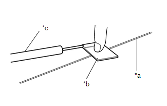
|
*a |
Defogger Wire |
|
*b |
Tin Foil |
|
*c |
Tester Probe |
(a) Turn the ignition switch to ON.
(b) Turn the defogger switch on.
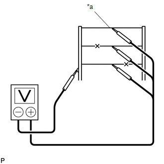
|
*a |
Center |
(c) Measure the voltage at the center of each defogger wire as shown in the illustration.
Standard Voltage:
|
Voltage |
Criteria |
|---|---|
|
Approximately 5 V |
Wire is not broken |
|
Approximately 10 or 0 V |
Wire is broken |
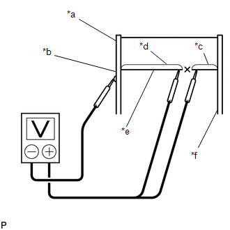
|
*a |
Ground Side |
|
*b |
Foil Strip |
|
*c |
Approximately 10 V |
|
*d |
0 V |
|
*e |
Broken Wire |
|
*f |
Battery Side |
HINT:
If there is approximately 10 V, the wire may be faulty between the center of the wire and the wire end on the battery side. If there is no voltage, the wire may be faulty between the center of the wire end and the wire end on the ground side.
(d) Place the voltmeter's positive (+) lead against the defogger wire on the battery side.
(e) Place the voltmeter's negative (-) lead with the foil strip against the wire on the ground side.
(f) Slide the positive (+) lead from the battery side to the ground side.
(g) The point where the voltage drops from approximately 10 V to 0 V is where the defogger wire is broken.
HINT:
If the defogger wire is not broken, the voltmeter indicates 0 V at the positive (+) end of the defogger wire and gradually increases to approximately 12 V as the meter probe moves to the other end.
Repair
REPAIR
PROCEDURE
1. REPAIR BACK DOOR GLASS
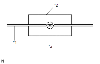
|
*1 |
Broken Wire |
|
*2 |
Masking Tape |
|
*a |
Repair Point |
(a) Clean the broken wire tips with grease, wax and silicone remover.
(b) Place masking tape along both sides of the wire.
(c) Thoroughly mix the repair agent.
|
(d) Using a fine tip brush, apply a small amount of the agent to the wire. |
|
(e) After a few minutes, remove the masking tape.
NOTICE:
Do not repair the defogger wire again for at least 24 hours.
 Rear Window Defogger System does not Operate
DESCRIPTION
When the rear window defogger switch on the air conditioning control assembly
is pressed, the operation signal is transmitted to the air conditioning amplifier
assembly via LIN commun ...

Other materials:
Toyota CH-R Service Manual > Front Bumper: Removal
REMOVAL
PROCEDURE
1. REMOVE RADIATOR COVER
(a) Remove the 2 hood bumper cushions.
(b) Remove the 4 clips.
(c) Disengage the guides to remove the radiator cover as shown in the illustration.
Remove in this Directio ...
Toyota CH-R Service Manual > Airbag System: Occupant Classification System Malfunction (B1650/32,B165A/32)
DESCRIPTION
The airbag sensor assembly and occupant detection ECU communicate via CAN communication.
When the occupant detection ECU stores DTC B1771, B1780, B1782, B1795, B1798,
B1799, U0125 or U0129, the airbag sensor assembly receives this information and
stores DTC B1650/32.
When the occu ...
Toyota C-HR (AX20) 2023-2026 Owner's Manual
Toyota CH-R Owners Manual
- For safety and security
- Instrument cluster
- Operation of each component
- Driving
- Interior features
- Maintenance and care
- When trouble arises
- Vehicle specifications
- For owners
Toyota CH-R Service Manual
- Introduction
- Maintenance
- Audio / Video
- Cellular Communication
- Navigation / Multi Info Display
- Park Assist / Monitoring
- Brake (front)
- Brake (rear)
- Brake Control / Dynamic Control Systems
- Brake System (other)
- Parking Brake
- Axle And Differential
- Drive Shaft / Propeller Shaft
- K114 Cvt
- 3zr-fae Battery / Charging
- Networking
- Power Distribution
- Power Assist Systems
- Steering Column
- Steering Gear / Linkage
- Alignment / Handling Diagnosis
- Front Suspension
- Rear Suspension
- Tire / Wheel
- Tire Pressure Monitoring
- Door / Hatch
- Exterior Panels / Trim
- Horn
- Lighting (ext)
- Mirror (ext)
- Window / Glass
- Wiper / Washer
- Door Lock
- Heating / Air Conditioning
- Interior Panels / Trim
- Lighting (int)
- Meter / Gauge / Display
- Mirror (int)
- Power Outlets (int)
- Pre-collision
- Seat
- Seat Belt
- Supplemental Restraint Systems
- Theft Deterrent / Keyless Entry

0.0066