Toyota CH-R Service Manual: Parts Location
PARTS LOCATION
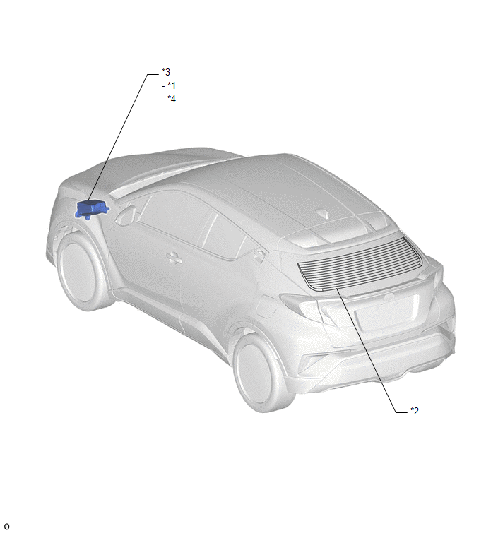
ILLUSTRATION
|
*1 |
DEF RELAY |
*2 |
BACK DOOR GLASS (REAR WINDOW DEFOGGER WIRE) |
|
*3 |
NO. 1 ENGINE ROOM RELAY BLOCK |
*4 |
DEF FUSE |
ILLUSTRATION
|
*A |
for TMMT Made |
*B |
for TMC Made |
|
*1 |
REAR WINDOW DEFOGGER SWITCH |
*2 |
DLC3 |
|
*3 |
AIR CONDITIONING AMPLIFIER ASSEMBLY |
*4 |
AIR CONDITIONING CONTROL ASSEMBLY |
|
*5 |
INSTRUMENT PANEL JUNCTION BLOCK ASSEMBLY - ECU-IG1 NO. 3 FUSE - ECU-IG1 NO. 4 FUSE |
- |
- |

 Precaution
PRECAUTION
IGNITION SWITCH EXPRESSIONS
(a) The type of ignition switch used on this model differs according to the specifications
of the vehicle. The expressions listed in the table below are used ...
Other materials:
Toyota CH-R Service Manual > Airbag System: Lost Communication with Front Airbag Sensor RH (B1612/83,B1613/83)
DESCRIPTION
The front airbag sensor RH circuit consists of the airbag sensor assembly and
front airbag sensor RH.
The front airbag sensor RH detects impacts to the vehicle and sends signals to
the airbag sensor assembly to determine if the airbags and pretensioners should
be deployed.
These ...
Toyota CH-R Service Manual > Back Door Courtesy Switch: Components
COMPONENTS
ILLUSTRATION
*A
w/ Package Tray Trim
*B
w/ Tonneau Cover
*1
BACK DOOR LOCK ASSEMBLY
*2
BACK DOOR LOCK COVER
*3
BACK DOOR SIDE GARNISH LH
*4
B ...
Toyota C-HR (AX20) 2023-2026 Owner's Manual
Toyota CH-R Owners Manual
- For safety and security
- Instrument cluster
- Operation of each component
- Driving
- Interior features
- Maintenance and care
- When trouble arises
- Vehicle specifications
- For owners
Toyota CH-R Service Manual
- Introduction
- Maintenance
- Audio / Video
- Cellular Communication
- Navigation / Multi Info Display
- Park Assist / Monitoring
- Brake (front)
- Brake (rear)
- Brake Control / Dynamic Control Systems
- Brake System (other)
- Parking Brake
- Axle And Differential
- Drive Shaft / Propeller Shaft
- K114 Cvt
- 3zr-fae Battery / Charging
- Networking
- Power Distribution
- Power Assist Systems
- Steering Column
- Steering Gear / Linkage
- Alignment / Handling Diagnosis
- Front Suspension
- Rear Suspension
- Tire / Wheel
- Tire Pressure Monitoring
- Door / Hatch
- Exterior Panels / Trim
- Horn
- Lighting (ext)
- Mirror (ext)
- Window / Glass
- Wiper / Washer
- Door Lock
- Heating / Air Conditioning
- Interior Panels / Trim
- Lighting (int)
- Meter / Gauge / Display
- Mirror (int)
- Power Outlets (int)
- Pre-collision
- Seat
- Seat Belt
- Supplemental Restraint Systems
- Theft Deterrent / Keyless Entry

0.0093