Toyota CH-R Service Manual: Inspection
INSPECTION
PROCEDURE
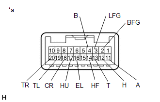
1. INSPECT HEADLIGHT DIMMER SWITCH ASSEMBLY
(a) Check the resistance.
|
(1) Measure the resistance according to the value(s) in the table below. Standard Resistance: Light Control Switch
|
|
 Removal
REMOVAL
CAUTION / NOTICE / HINT
The necessary procedures (adjustment, calibration, initialization or registration)
that must be performed after parts are removed and installed, or replaced during ...
 Installation
INSTALLATION
PROCEDURE
1. INSTALL HEADLIGHT DIMMER SWITCH ASSEMBLY
(a) Engage the claws to install the headlight dimmer switch assembly as shown
in the illustration.
Instal ...
Other materials:
Toyota CH-R Service Manual > Outer Rear View Mirror Glass: Installation
INSTALLATION
CAUTION / NOTICE / HINT
HINT:
Use the same procedure for the RH side and LH side.
The following procedure is for the LH side.
PROCEDURE
1. INSTALL OUTER MIRROR
(a) Connect the 2 connectors.
(b) w/ Blind Spot Monitor:
(1) Connect the connector.
(c) Engage the c ...
Toyota CH-R Service Manual > Condenser: Disassembly
DISASSEMBLY
PROCEDURE
1. REMOVE COOLER DRYER (for VALEO Made)
(a) Using a T55 "TORX" socket wrench, remove the cap from the modulator.
*a
Modulator
...
Toyota C-HR (AX20) 2023-2026 Owner's Manual
Toyota CH-R Owners Manual
- For safety and security
- Instrument cluster
- Operation of each component
- Driving
- Interior features
- Maintenance and care
- When trouble arises
- Vehicle specifications
- For owners
Toyota CH-R Service Manual
- Introduction
- Maintenance
- Audio / Video
- Cellular Communication
- Navigation / Multi Info Display
- Park Assist / Monitoring
- Brake (front)
- Brake (rear)
- Brake Control / Dynamic Control Systems
- Brake System (other)
- Parking Brake
- Axle And Differential
- Drive Shaft / Propeller Shaft
- K114 Cvt
- 3zr-fae Battery / Charging
- Networking
- Power Distribution
- Power Assist Systems
- Steering Column
- Steering Gear / Linkage
- Alignment / Handling Diagnosis
- Front Suspension
- Rear Suspension
- Tire / Wheel
- Tire Pressure Monitoring
- Door / Hatch
- Exterior Panels / Trim
- Horn
- Lighting (ext)
- Mirror (ext)
- Window / Glass
- Wiper / Washer
- Door Lock
- Heating / Air Conditioning
- Interior Panels / Trim
- Lighting (int)
- Meter / Gauge / Display
- Mirror (int)
- Power Outlets (int)
- Pre-collision
- Seat
- Seat Belt
- Supplemental Restraint Systems
- Theft Deterrent / Keyless Entry

0.0087