Toyota CH-R Service Manual: Tire Pressure Monitor ECU Communication Stop (C2179/79)
DESCRIPTION
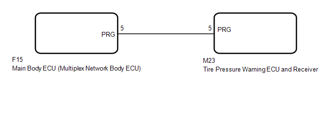
The main body ECU (multiplex network body ECU) sends signals to the tire pressure warning ECU and receiver via a direct line.
|
DTC No. |
Detection Item |
DTC Detection Condition |
Trouble Area |
Note |
|---|---|---|---|---|
|
C2179/79 |
Tire Pressure Monitor ECU Communication Stop |
Communication between the main body ECU (multiplex network body ECU) and tire pressure warning ECU and receiver is interrupted for 10 seconds or more. |
|
- |
WIRING DIAGRAM
CAUTION / NOTICE / HINT
NOTICE:
- When replacing the tire pressure warning ECU and receiver, read the
transmitter IDs stored in the old ECU using the Techstream and write them
down before removal.
Click here
.gif)
- It is necessary to perform initialization
after registration
of the transmitter IDs into the tire pressure warning ECU and receiver after
the ECU and/or one of the valve and transmitters has been replaced.
- If the main body ECU (multiplex network body ECU) is replaced, refer
to Registration.*
*: w/ Smart Key System
Click here
PROCEDURE
|
1. |
CHECK HARNESS AND CONNECTOR (TIRE PRESSURE WARNING ECU AND RECEIVER - MAIN BODY ECU (MULTIPLEX NETWORK BODY ECU)) |
(a) Turn the ignition switch off.
(b) Disconnect the M23 tire pressure warning ECU and receiver connector.
(c) Disconnect the F15 main body ECU (multiplex network body ECU) connector.
(d) Measure the resistance according to the value(s) in the table below.
Standard Resistance:
|
Tester Connection |
Condition |
Specified Condition |
|---|---|---|
|
M23-5 (PRG) - F15-5 (PRG) |
Always |
Below 1 Ω |
|
M23-5 (PRG) or F15-5 (PRG) - Body ground |
Always |
10 kΩ or higher |
| NG | .gif) |
REPAIR OR REPLACE HARNESS OR CONNECTOR |
|
.gif)
|
2. |
REPLACE TIRE PRESSURE WARNING ECU AND RECEIVER |
(a) Replace the tire pressure warning ECU and receiver.
Click here
|
|
3. |
CHECK DTC OUTPUT |
(a) Clear the DTCs.
Click here
(b) Turn the ignition switch off.
(c) Turn the ignition switch to ON.
(d) Check for DTCs.
Click here
OK:
DTC C2179/79 is not output.
| OK | |
END |
| NG | |
REPLACE MAIN BODY ECU (MULTIPLEX NETWORK BODY ECU)
|
 Initialization not Completed (C2177/77)
DESCRIPTION
Initialization is necessary if one of the following occurs:
The tire pressure warning ECU and receiver is replaced.
A tire pressure warning valve and transmitter is replaced. ...
 Transmitter ID1 Error (C2141/41-C2145/45)
DESCRIPTION
The tire pressure warning valve and transmitters that are installed in the tire
and wheel assemblies measure the tire pressures. The measured values are transmitted
to the tire pressu ...
Other materials:
Toyota CH-R Service Manual > Lighting System: How To Proceed With Troubleshooting
CAUTION / NOTICE / HINT
HINT:
Use the following procedure to troubleshoot the lighting system.
*: Use the Techstream.
PROCEDURE
1.
VEHICLE BROUGHT TO WORKSHOP
NEXT
2. ...
Toyota CH-R Service Manual > Audio And Visual System(for Radio And Display Type): Parts Location
PARTS LOCATION
ILLUSTRATION
*1
MAP LIGHT ASSEMBLY (TELEPHONE MICROPHONE ASSEMBLY)
*2
SKID CONTROL ECU (BRAKE ACTUATOR ASSEMBLY)
ILLUSTRATION
*1
FRONT NO. 1 SPEAKER ASSEMBLY LH
*2
FRONT NO. 1 SPEA ...
Toyota C-HR (AX20) 2023-2026 Owner's Manual
Toyota CH-R Owners Manual
- For safety and security
- Instrument cluster
- Operation of each component
- Driving
- Interior features
- Maintenance and care
- When trouble arises
- Vehicle specifications
- For owners
Toyota CH-R Service Manual
- Introduction
- Maintenance
- Audio / Video
- Cellular Communication
- Navigation / Multi Info Display
- Park Assist / Monitoring
- Brake (front)
- Brake (rear)
- Brake Control / Dynamic Control Systems
- Brake System (other)
- Parking Brake
- Axle And Differential
- Drive Shaft / Propeller Shaft
- K114 Cvt
- 3zr-fae Battery / Charging
- Networking
- Power Distribution
- Power Assist Systems
- Steering Column
- Steering Gear / Linkage
- Alignment / Handling Diagnosis
- Front Suspension
- Rear Suspension
- Tire / Wheel
- Tire Pressure Monitoring
- Door / Hatch
- Exterior Panels / Trim
- Horn
- Lighting (ext)
- Mirror (ext)
- Window / Glass
- Wiper / Washer
- Door Lock
- Heating / Air Conditioning
- Interior Panels / Trim
- Lighting (int)
- Meter / Gauge / Display
- Mirror (int)
- Power Outlets (int)
- Pre-collision
- Seat
- Seat Belt
- Supplemental Restraint Systems
- Theft Deterrent / Keyless Entry

0.008