Toyota CH-R Service Manual: Initialization Switch (for Test Mode DTC) (C2198/98)
DESCRIPTION
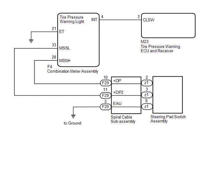
The switch circuit inside the combination meter assembly turns on and off according to the steering pad switch assembly operation.
During test mode, when the steering pad switch assembly is operated, "TPMS" is selected on the multi-information display and the "ENTER" switch (steering pad switch assembly) is pressed, the tire pressure warning light illuminates, and when the "ENTER" switch (steering pad switch assembly) is not pressed, the tire pressure warning light blinks at 0.125 second intervals.
|
DTC No. |
Detection Item |
DTC Detection Condition |
Trouble Area |
Note |
|---|---|---|---|---|
|
C2198/98 |
Initialization Switch (for Test Mode DTC) |
Test mode procedure is performed. |
|
- |
WIRING DIAGRAM
CAUTION / NOTICE / HINT
NOTICE:
- When replacing the tire pressure warning ECU and receiver, read the
transmitter IDs stored in the old ECU using the Techstream and write them
down before removal.
Click here
.gif)
- It is necessary to perform initialization
after registration
of the transmitter IDs into the tire pressure warning ECU and receiver if
the ECU and/or one of the valve and transmitters has been replaced.
PROCEDURE
|
1. |
INSPECT STEERING PAD SWITCH ASSEMBLY |
(a) Remove the steering pad switch assembly.
Click here
(b) Inspect the steering pad switch assembly.
Click here
| NG | .gif) |
REPLACE STEERING PAD SWITCH ASSEMBLY |
|
.gif)
|
2. |
INSPECT SPIRAL CABLE SUB-ASSEMBLY |
(a) Remove the spiral cable sub-assembly.
Click here
(b) Inspect the spiral cable sub-assembly.
Click here
| NG | |
REPLACE SPIRAL CABLE SUB-ASSEMBLY
|
|
|
3. |
CHECK HARNESS AND CONNECTOR (SPIRAL CABLE SUB-ASSEMBLY - COMBINATION METER ASSEMBLY) |
(a) Disconnect the F29 spiral cable sub-assembly connector.
(b) Disconnect the F4 combination meter assembly connector.
(c) Measure the resistance according to the value(s) in the table below.
Standard Resistance:
|
Tester Connection |
Condition |
Specified Condition |
|---|---|---|
|
F29-10 (+DP) - F4-28 (MSM+) |
Always |
Below 1 Ω |
|
F29-10 (+DP) or F4-28 (MSM+) - Body ground |
Always |
10 kΩ or higher |
|
F29-11 (+DP2) - F4-33 (MSSL) |
Always |
Below 1 Ω |
|
F29-11 (+DP2) or F4-33 (MSSL) - Body ground |
Always |
10 kΩ or higher |
| NG | |
REPAIR OR REPLACE HARNESS OR CONNECTOR |
|
|
4. |
CHECK HARNESS AND CONNECTOR (COMBINATION METER ASSEMBLY - TIRE PRESSURE WARNING ECU AND RECEIVER) |
(a) Disconnect the M23 tire pressure warning ECU and receiver connector.
(b) Disconnect the F4 combination meter assembly connector.
(c) Measure the resistance according to the value(s) in the table below.
Standard Resistance:
|
Tester Connection |
Condition |
Specified Condition |
|---|---|---|
|
M23-3 (CLSW) - F4-4 (INT) |
Always |
Below 1 Ω |
|
M23-3 (CLSW) or F4-4 (INT) - Body ground |
Always |
10 kΩ or higher |
|
F4-21 (ET) - Body ground |
Always |
Below 1 Ω |
| NG | |
REPAIR OR REPLACE HARNESS OR CONNECTOR |
|
|
5. |
CHECK TERMINAL VOLTAGE (INT) |
(a) Disconnect the F4 combination meter assembly connector.
(b) Measure the voltage according to the value(s) in the table below.
Standard Voltage:
|
Tester Connection |
Condition |
Specified Condition |
|---|---|---|
|
F4-4 (INT) - Body ground |
Ignition switch to ON |
8 to 15 V |
| OK | |
GO TO METER / GAUGE SYSTEM |
| NG | |
REPLACE TIRE PRESSURE WARNING ECU AND RECEIVER |
 Transmitter ID not Received in Main Mode (C2126/26)
DESCRIPTION
After all IDs are registered, DTC C2126/26 is stored in the tire pressure warning
ECU and receiver and the tire pressure warning light blinks for 1 minute and then
illuminates.
When ...
 Initialization not Completed (C2177/77)
DESCRIPTION
Initialization is necessary if one of the following occurs:
The tire pressure warning ECU and receiver is replaced.
A tire pressure warning valve and transmitter is replaced. ...
Other materials:
Toyota CH-R Service Manual > General Maintenance: Engine
ENGINE
HINT:
Perform these procedures after the engine has cooled down.
INSPECT DRIVE BELT
(a) Check the drive belt.
Click here
INSPECT ENGINE OIL AND OIL FILTER
(a) Check the engine oil and oil filter.
Click here
INSPECT ENGINE COOLANT
(a) Check the engine coolant.
Click here
...
Toyota CH-R Service Manual > Lighting (int): Map Light Bulb
Replacement
REPLACEMENT
PROCEDURE
1. REMOVE NO. 1 MAP LIGHT LENS
Click here
2. REMOVE MAP LIGHT BULB
(a) Remove the 2 map light bulbs as shown in the illustration.
Remove in this Direction
3. INSTALL MAP LIGHT BULB
(a) Install the 2 map light bulbs as show ...
Toyota C-HR (AX20) 2023-2026 Owner's Manual
Toyota CH-R Owners Manual
- For safety and security
- Instrument cluster
- Operation of each component
- Driving
- Interior features
- Maintenance and care
- When trouble arises
- Vehicle specifications
- For owners
Toyota CH-R Service Manual
- Introduction
- Maintenance
- Audio / Video
- Cellular Communication
- Navigation / Multi Info Display
- Park Assist / Monitoring
- Brake (front)
- Brake (rear)
- Brake Control / Dynamic Control Systems
- Brake System (other)
- Parking Brake
- Axle And Differential
- Drive Shaft / Propeller Shaft
- K114 Cvt
- 3zr-fae Battery / Charging
- Networking
- Power Distribution
- Power Assist Systems
- Steering Column
- Steering Gear / Linkage
- Alignment / Handling Diagnosis
- Front Suspension
- Rear Suspension
- Tire / Wheel
- Tire Pressure Monitoring
- Door / Hatch
- Exterior Panels / Trim
- Horn
- Lighting (ext)
- Mirror (ext)
- Window / Glass
- Wiper / Washer
- Door Lock
- Heating / Air Conditioning
- Interior Panels / Trim
- Lighting (int)
- Meter / Gauge / Display
- Mirror (int)
- Power Outlets (int)
- Pre-collision
- Seat
- Seat Belt
- Supplemental Restraint Systems
- Theft Deterrent / Keyless Entry

0.0109