Toyota CH-R Service Manual: Installation
INSTALLATION
PROCEDURE
1. INSTALL REAR STABILIZER BUSHING
(a) Install the 2 rear stabilizer bushings to the rear stabilizer bar.
NOTICE:
Be sure to install the rear stabilizer bushings so that each cutout faces the front of the vehicle.
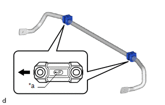
2. INSTALL REAR NO. 1 STABILIZER BAR BRACKET
(a) Install the 2 rear No. 1 stabilizer bar brackets to the 2 rear stabilizer bushings.
NOTICE:
Be sure to install the rear No. 1 stabilizer bar brackets so that each arrow mark faces the front of the vehicle.
|
*a |
Arrow Mark |
.png) |
Front of the Vehicle |
3. INSTALL REAR STABILIZER BAR
|
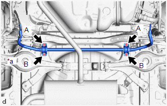
(a) Install the rear stabilizer bar, 2 rear No. 1 stabilizer bar brackets and 2 rear stabilizer bushings to the rear suspension member sub-assembly with the 4 bolts. Torque: 78 N·m {795 kgf·cm, 58 ft·lbf} NOTICE:
|
|
4. STABILIZE SUSPENSION
Click here
.gif)
5. INSTALL REAR STABILIZER LINK ASSEMBLY LH
|
(a) Install the rear stabilizer link assembly LH with the nut (A). Torque: 75 N·m {765 kgf·cm, 55 ft·lbf} HINT: If the ball joint turns together with the nut, use a 6 mm hexagon socket wrench to hold the stud bolt. |
|
.png)
(b) Install the rear stabilizer link assembly LH with the bolt and nut (B).
Torque:
75 N·m {765 kgf·cm, 55 ft·lbf}
NOTICE:
Because the bolt has its own stopper, do not turn the bolt. Tighten the nut with the bolt secured.
6. INSTALL REAR STABILIZER LINK ASSEMBLY RH
HINT:
Perform the same procedure as for the LH side.
7. INSTALL REAR WHEEL
Click here
 Inspection
INSPECTION
PROCEDURE
1. INSPECT REAR STABILIZER LINK ASSEMBLY
(a) Inspect the turning torque of the ball joint.
(1) Secure the rear stabilizer link assembly in a vise using aluminum plates.
NOT ...

Other materials:
Toyota CH-R Service Manual > Rear Combination Light Assembly(for Led Type): Removal
REMOVAL
CAUTION / NOTICE / HINT
HINT:
Use the same procedure for the RH side and LH side.
The following procedure is for the LH side.
PROCEDURE
1. REMOVE REAR COMBINATION LIGHT COVER
(a) Disengage the claws to remove the rear combination light cover as shown in
the illustra ...
Toyota CH-R Service Manual > Front Drive Shaft Assembly: Disassembly
DISASSEMBLY
PROCEDURE
1. SEPARATE FRONT NO. 2 AXLE INBOARD JOINT BOOT CLAMP
(a) Secure the drive shaft in a vise between aluminum plates.
NOTICE:
Do not overtighten the vise.
(b) Using pliers, separate the front No. 2 axle inboard joint boot clamp.
...
Toyota C-HR (AX20) 2023-2026 Owner's Manual
Toyota CH-R Owners Manual
- For safety and security
- Instrument cluster
- Operation of each component
- Driving
- Interior features
- Maintenance and care
- When trouble arises
- Vehicle specifications
- For owners
Toyota CH-R Service Manual
- Introduction
- Maintenance
- Audio / Video
- Cellular Communication
- Navigation / Multi Info Display
- Park Assist / Monitoring
- Brake (front)
- Brake (rear)
- Brake Control / Dynamic Control Systems
- Brake System (other)
- Parking Brake
- Axle And Differential
- Drive Shaft / Propeller Shaft
- K114 Cvt
- 3zr-fae Battery / Charging
- Networking
- Power Distribution
- Power Assist Systems
- Steering Column
- Steering Gear / Linkage
- Alignment / Handling Diagnosis
- Front Suspension
- Rear Suspension
- Tire / Wheel
- Tire Pressure Monitoring
- Door / Hatch
- Exterior Panels / Trim
- Horn
- Lighting (ext)
- Mirror (ext)
- Window / Glass
- Wiper / Washer
- Door Lock
- Heating / Air Conditioning
- Interior Panels / Trim
- Lighting (int)
- Meter / Gauge / Display
- Mirror (int)
- Power Outlets (int)
- Pre-collision
- Seat
- Seat Belt
- Supplemental Restraint Systems
- Theft Deterrent / Keyless Entry

0.0092