Toyota CH-R Service Manual: Components
COMPONENTS
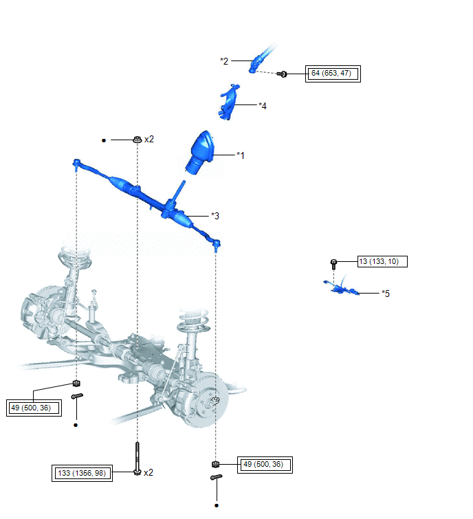
ILLUSTRATION
|
*1 |
NO. 1 STEERING COLUMN HOLE COVER SUB-ASSEMBLY |
*2 |
NO. 2 STEERING INTERMEDIATE SHAFT ASSEMBLY |
|
*3 |
STEERING LINK ASSEMBLY |
*4 |
COLUMN HOLE COVER SILENCER SHEET |
|
*5 |
WIRING HARNESS CLAMP BRACKET |
- |
- |
.png) |
Tightening torque for "Major areas involving basic vehicle performance such as moving/turning/stopping" : N*m (kgf*cm, ft.*lbf) |
.png) |
N*m (kgf*cm, ft.*lbf): Specified torque |
|
● |
Non-reusable part |
- |
- |
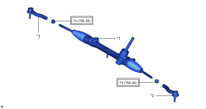
ILLUSTRATION
|
*1 |
STEERING GEAR ASSEMBLY |
*2 |
TIE ROD END SUB-ASSEMBLY LH |
|
*3 |
TIE ROD END SUB-ASSEMBLY RH |
- |
- |
|
|
Tightening torque for "Major areas involving basic vehicle performance such as moving/turning/stopping" : N*m (kgf*cm, ft.*lbf) |
- |
- |
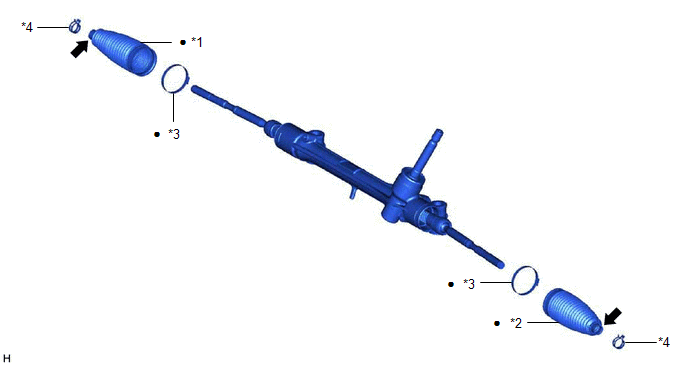
ILLUSTRATION
|
*1 |
NO. 1 STEERING RACK BOOT |
*2 |
NO. 2 STEERING RACK BOOT |
|
*3 |
STEERING RACK BOOT CLAMP |
*4 |
STEERING RACK BOOT CLIP |
|
● |
Non-reusable part |
.png) |
Lithium soap base glycol grease |
 Steering Gear
...
 Removal
REMOVAL
CAUTION / NOTICE / HINT
The necessary procedures (adjustment, calibration, initialization, or registration)
that must be performed after parts are removed and installed, or replaced during ...
Other materials:
Toyota CH-R Service Manual > Quarter Garnish: Disassembly
DISASSEMBLY
CAUTION / NOTICE / HINT
HINT:
Use the same procedure for the RH side and LH side.
The following procedure is for the LH side.
PROCEDURE
1. REMOVE QUARTER GARNISH MOULDING
(a) Remove the quarter garnish moulding.
...
Toyota CH-R Service Manual > Horn: Horn
Components
COMPONENTS
ILLUSTRATION
*1
LOW PITCHED HORN ASSEMBLY
*2
NO.1 RADIATOR GRILLE RETAINER
*3
NO.1 RADIATOR TO SUPPORT SEAL
-
-
N*m (kgf*cm, ft.*lbf): Specified torque ...
Toyota C-HR (AX20) 2023-2026 Owner's Manual
Toyota CH-R Owners Manual
- For safety and security
- Instrument cluster
- Operation of each component
- Driving
- Interior features
- Maintenance and care
- When trouble arises
- Vehicle specifications
- For owners
Toyota CH-R Service Manual
- Introduction
- Maintenance
- Audio / Video
- Cellular Communication
- Navigation / Multi Info Display
- Park Assist / Monitoring
- Brake (front)
- Brake (rear)
- Brake Control / Dynamic Control Systems
- Brake System (other)
- Parking Brake
- Axle And Differential
- Drive Shaft / Propeller Shaft
- K114 Cvt
- 3zr-fae Battery / Charging
- Networking
- Power Distribution
- Power Assist Systems
- Steering Column
- Steering Gear / Linkage
- Alignment / Handling Diagnosis
- Front Suspension
- Rear Suspension
- Tire / Wheel
- Tire Pressure Monitoring
- Door / Hatch
- Exterior Panels / Trim
- Horn
- Lighting (ext)
- Mirror (ext)
- Window / Glass
- Wiper / Washer
- Door Lock
- Heating / Air Conditioning
- Interior Panels / Trim
- Lighting (int)
- Meter / Gauge / Display
- Mirror (int)
- Power Outlets (int)
- Pre-collision
- Seat
- Seat Belt
- Supplemental Restraint Systems
- Theft Deterrent / Keyless Entry

0.0085