Toyota CH-R Service Manual: System Diagram
SYSTEM DIAGRAM
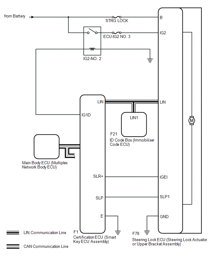 Circuit Description
|
Component |
Outline |
|---|---|
|
Steering Lock ECU (Steering Lock Actuator or Upper Bracket Assembly) |
|
|
Certification ECU (Smart Key ECU Assembly) |
|
|
ID Code Box (Immobiliser Code ECU) |
Receives immobiliser set and unset commands from the certification ECU (smart key ECU assembly) via LIN communication and sends them to the ECM. |
 System Description
SYSTEM DESCRIPTION
UNLOCK OPERATION CONDITIONS FOR STEERING LOCK
(a) When the following condition is met, the unlock operation is performed.
The engine switch is on (ACC) or on (IG).
HINT ...
 How To Proceed With Troubleshooting
CAUTION / NOTICE / HINT
HINT:
Use the following procedures to troubleshoot the steering lock system.
*: Use the Techstream.
PROCEDURE
1.
VEHICLE BROUGHT ...
Other materials:
Toyota CH-R Service Manual > Brake (front): Front Brake Flexible Hose
Components
COMPONENTS
ILLUSTRATION
*1
FRONT FLEXIBLE HOSE
*2
GASKET
*3
BRAKE LINE
*4
FRONT SPEED SENSOR
*5
UNION BOLT
-
-
T ...
Toyota CH-R Service Manual > Vehicle Stability Control System: Brake Warning Light does not Come ON
DESCRIPTION
The skid control ECU (brake actuator assembly) is connected to the combination
meter assembly via CAN communication.
CAUTION / NOTICE / HINT
NOTICE:
When replacing the skid control ECU (brake actuator assembly), perform
system variant learning.
Click here
...
Toyota C-HR (AX20) 2023-2026 Owner's Manual
Toyota CH-R Owners Manual
- For safety and security
- Instrument cluster
- Operation of each component
- Driving
- Interior features
- Maintenance and care
- When trouble arises
- Vehicle specifications
- For owners
Toyota CH-R Service Manual
- Introduction
- Maintenance
- Audio / Video
- Cellular Communication
- Navigation / Multi Info Display
- Park Assist / Monitoring
- Brake (front)
- Brake (rear)
- Brake Control / Dynamic Control Systems
- Brake System (other)
- Parking Brake
- Axle And Differential
- Drive Shaft / Propeller Shaft
- K114 Cvt
- 3zr-fae Battery / Charging
- Networking
- Power Distribution
- Power Assist Systems
- Steering Column
- Steering Gear / Linkage
- Alignment / Handling Diagnosis
- Front Suspension
- Rear Suspension
- Tire / Wheel
- Tire Pressure Monitoring
- Door / Hatch
- Exterior Panels / Trim
- Horn
- Lighting (ext)
- Mirror (ext)
- Window / Glass
- Wiper / Washer
- Door Lock
- Heating / Air Conditioning
- Interior Panels / Trim
- Lighting (int)
- Meter / Gauge / Display
- Mirror (int)
- Power Outlets (int)
- Pre-collision
- Seat
- Seat Belt
- Supplemental Restraint Systems
- Theft Deterrent / Keyless Entry

0.0068