Toyota CH-R Service Manual: Heated Steering Wheel System
Parts Location
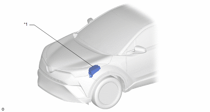
PARTS LOCATION
ILLUSTRATION
|
*1 |
NO. 1 ENGINE ROOM RELAY BLOCK - STRG HTR FUSE |
- |
- |
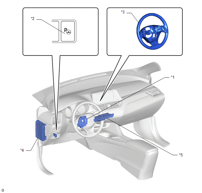
ILLUSTRATION
|
*1 |
SPIRAL CABLE WITH SENSOR SUB-ASSEMBLY |
*2 |
STEERING HEATER SWITCH |
|
*3 |
STEERING WHEEL ASSEMBLY - STEERING WHEEL HEATER UNIT |
*4 |
INSTRUMENT PANEL JUNCTION BLOCK ASSEMBLY - ECU-IG1 NO. 4 FUSE |
|
*5 |
NO. 4 RELAY BLOCK ASSEMBLY - STRG HTR RELAY |
- |
- |
Precaution
PRECAUTION
HANDLING PRECAUTIONS FOR SRS AIRBAG SYSTEM
(a) This vehicle is equipped with a Supplemental Restraint System (SRS). Failure to carry out service operations in the correct sequence could cause the SRS to unexpectedly deploy during servicing. This may cause a serious accident.
Before servicing (including inspection, replacement, removal and installation of parts), be sure to read the precautionary notices for Supplemental Restraint System.
Click here
.gif)
System Diagram
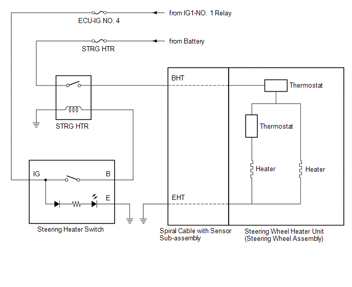
SYSTEM DIAGRAM
System Description
SYSTEM DESCRIPTION
HEATED STEERING WHEEL SYSTEM
(a) The steering heater warms up the steering wheel when the steering heater switch is turned on.
(b) The steering heater uses a control thermostat inside the steering wheel to maintain the steering wheel at the specified temperature.
OPERATION DESCRIPTION
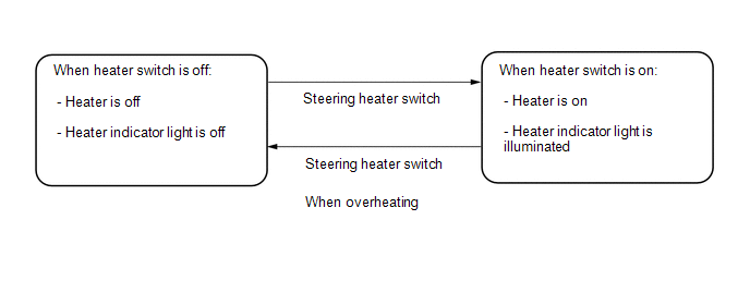
(a) When the steering heater switch is turned on with the ignition switch ON, the heater indicator light in the combination meter illuminates and the heater inside the steering wheel operates. If the steering heater switch is pushed again, the heater indicator light in the combination meter turns off and the heater stops operating.
(b) A control thermostat and an additional thermostat used as a safety device to prevent overheating are installed inside the steering wheel.
CONTROL DESCRIPTION
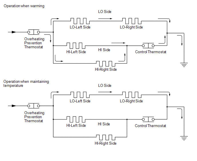
(a) When the steering heater switch is turned on, current flows to the LO and HI sides, starting the warming operation to warm the steering wheel.
(b) When the temperature of the steering wheel reaches the operation temperature of the control thermostat, the control thermostat stops the flow of current to the HI side, only allowing current to flow to the LO side and thereby maintaining the temperature of the steering wheel.
(c) While operating to maintain the temperature of the steering wheel, if the temperature drops to the operation temperature of the control thermostat, the control thermostat restarts the flow of current to both the LO and HI sides to warm the steering wheel.
(d) While the steering heater switch is on, the control thermostat automatically stops and restarts the flow of current to the HI side according to the temperature of the steering wheel, continuously maintaining the specified temperature.
(e) If a malfunction occurs in the steering heater circuit and the temperature exceeds the specified temperature, the overheating prevention thermostat stops the flow of current to the circuit, the heater indicator light in the combination meter assembly turns off and the heater stops operating.
Problem Symptoms Table
PROBLEM SYMPTOMS TABLE
HINT:
Use the table below to help determine the cause of problem symptoms. If multiple suspected areas are listed, the potential causes of the symptoms are listed in order of probability in the "Suspected Area" column of the table. Check each symptom by checking the suspected areas in the order they are listed. Replace parts as necessary.
Heated Steering Wheel System|
Symptom |
Suspected Area |
Link |
|---|---|---|
|
Steering wheel does not heat up when heated steering wheel switch is pressed |
STRG HTR fuse |
- |
|
ECU-IG1 NO. 4 fuse |
- |
|
|
STRG HTR relay |
- |
|
|
Steering heater switch |
|
|
|
Spiral cable with sensor sub-assembly |
|
|
|
Steering wheel heater unit (steering wheel assembly) |
|
.gif)
 Steering Column
...

Other materials:
Toyota CH-R Service Manual > Id Code Box: Removal
REMOVAL
CAUTION / NOTICE / HINT
The necessary procedures (adjustment, calibration, initialization, or registration)
that must be performed after parts are removed, installed, or replaced during the
ID code box (immobiliser code ECU) removal/installation are shown below.
Necessary Procedure Af ...
Toyota CH-R Service Manual > Maintenance: 3zr-fae Drive Belt
Components
COMPONENTS
ILLUSTRATION
*1
FAN AND GENERATOR V BELT
*2
REAR ENGINE UNDER COVER RH
Removal
REMOVAL
PROCEDURE
1. REMOVE REAR ENGINE UNDER COVER RH
(a) Remove the 2 screws, 6 clips and rear engine under cover RH fr ...
Toyota C-HR (AX20) 2023-2026 Owner's Manual
Toyota CH-R Owners Manual
- For safety and security
- Instrument cluster
- Operation of each component
- Driving
- Interior features
- Maintenance and care
- When trouble arises
- Vehicle specifications
- For owners
Toyota CH-R Service Manual
- Introduction
- Maintenance
- Audio / Video
- Cellular Communication
- Navigation / Multi Info Display
- Park Assist / Monitoring
- Brake (front)
- Brake (rear)
- Brake Control / Dynamic Control Systems
- Brake System (other)
- Parking Brake
- Axle And Differential
- Drive Shaft / Propeller Shaft
- K114 Cvt
- 3zr-fae Battery / Charging
- Networking
- Power Distribution
- Power Assist Systems
- Steering Column
- Steering Gear / Linkage
- Alignment / Handling Diagnosis
- Front Suspension
- Rear Suspension
- Tire / Wheel
- Tire Pressure Monitoring
- Door / Hatch
- Exterior Panels / Trim
- Horn
- Lighting (ext)
- Mirror (ext)
- Window / Glass
- Wiper / Washer
- Door Lock
- Heating / Air Conditioning
- Interior Panels / Trim
- Lighting (int)
- Meter / Gauge / Display
- Mirror (int)
- Power Outlets (int)
- Pre-collision
- Seat
- Seat Belt
- Supplemental Restraint Systems
- Theft Deterrent / Keyless Entry

0.008