Toyota CH-R Service Manual: Open in Bus 4 Main Bus Line
DESCRIPTION
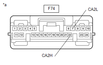
There may be an open circuit in one of the CAN main bus lines when the resistance between terminals 22 (CA2H) and 7 (CA2L) of the central gateway ECU (network gateway ECU) is 70 Ω or higher.
|
Symptom |
Trouble Area |
|---|---|
|
Resistance between terminals 22 (CA2H) and 7 (CA2L) of the central gateway ECU (network gateway ECU) is 70 Ω or higher. |
|
This malfunction is not related to the lines of a CAN branch or to ECUs or sensors connected to a CAN branch.
WIRING DIAGRAM
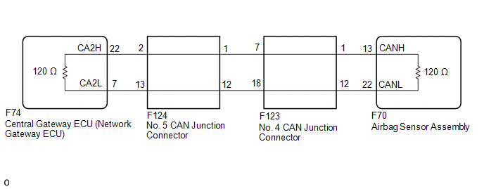
CAUTION / NOTICE / HINT
NOTICE:
- Because the order of diagnosis is important to allow correct diagnosis,
make sure to begin troubleshooting using How to Proceed with Troubleshooting
when CAN communication system related DTCs are output.
Click here
.gif)
.gif)
- Before measuring the resistance of the CAN bus, turn the ignition switch off and leave the vehicle for 1 minute or more without operating the key or any switches, or opening or closing the doors. After that, disconnect the cable from the negative (-) battery terminal and leave the vehicle for 1 minute or more before measuring the resistance.
- After turning the ignition switch off, waiting time may be required
before disconnecting the cable from the negative (-) battery terminal. Therefore,
make sure to read the disconnecting the cable from the negative (-) battery
terminal notices before proceeding with work.
Click here
.gif)
.gif)
- After performing repairs, perform the DTC check procedure and confirm
that the DTCs are not output again.
DTC check procedure: Turn the blind spot monitor system on using the blind spot monitor main switch (ON/OFF switch), turn the cruise control main switch on, turn the LDA main switch on and then drive the vehicle at a speed of 60 km/h (37 mph) or more for approximately 5 minutes or more.
- After the repair, perform the CAN bus check and check that all the ECUs
and sensors connected to the CAN communication system are displayed as normal.
Click here
.gif)
.gif)
.gif)
HINT:
- Before disconnecting related connectors for inspection, push in on each connector body to check that the connector is not loose or disconnected.
- When a connector is disconnected, check that the terminals and connector body are not cracked, deformed or corroded.
PROCEDURE
|
1. |
CHECK FOR OPEN IN CAN MAIN BUS LINES (NO. 5 CAN JUNCTION CONNECTOR) |
(a) Disconnect the cable from the negative (-) battery terminal.
(b) Disconnect the No. 5 CAN junction connector.
|
(c) Measure the resistance according to the value(s) in the table below. Standard Resistance:
|
|
|
Result |
Proceed to |
|---|---|
|
OK |
A |
|
NG (Line to central gateway ECU (network gateway ECU)) |
B |
|
NG (Line to No. 4 CAN junction connector) |
C |
| A | .gif) |
REPLACE NO. 5 CAN JUNCTION CONNECTOR |
| C | .gif) |
GO TO STEP 3 |
|
|
2. |
CHECK FOR OPEN IN CAN MAIN BUS LINES (CENTRAL GATEWAY ECU (NETWORK GATEWAY ECU) - NO. 5 CAN JUNCTION CONNECTOR) |
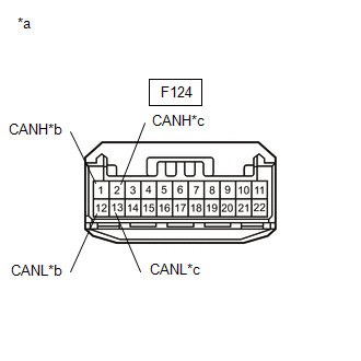
(a) Reconnect the F124 No. 5 CAN junction connector.
(b) Disconnect the F74 central gateway ECU (network gateway ECU) connector.
|
(c) Measure the resistance according to the value(s) in the table below. Standard Resistance:
|
|
| OK | .gif) |
REPLACE CENTRAL GATEWAY ECU (NETWORK GATEWAY ECU) |
| NG | .gif) |
REPAIR OR REPLACE CAN MAIN BUS LINES OR CONNECTOR (CENTRAL GATEWAY ECU (NETWORK GATEWAY ECU) - NO. 5 CAN JUNCTION CONNECTOR) |
|
3. |
CHECK FOR OPEN IN CAN MAIN BUS LINES (NO. 4 CAN JUNCTION CONNECTOR) |
(a) Reconnect the F124 No. 5 CAN junction connector.
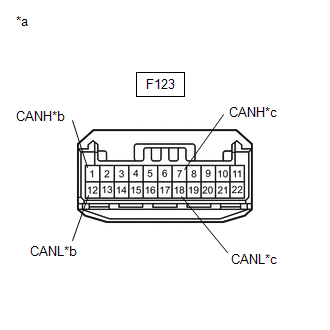
(b) Disconnect the No. 4 CAN junction connector.
|
(c) Measure the resistance according to the value(s) in the table below. Standard Resistance:
|
|
|
Result |
Proceed to |
|---|---|
|
OK |
A |
|
NG (Line to No. 5 CAN junction connector) |
B |
|
NG (Line to Airbag sensor assembly) |
C |
| A | .gif) |
REPLACE NO. 4 CAN JUNCTION CONNECTOR |
| B | .gif) |
REPAIR OR REPLACE CAN MAIN BUS LINES OR CONNECTOR (NO. 4 CAN JUNCTION CONNECTOR - NO. 5 CAN JUNCTION CONNECTOR) |
|
|
4. |
CHECK FOR OPEN IN CAN MAIN BUS LINES (AIRBAG SENSOR ASSEMBLY - NO. 4 CAN JUNCTION CONNECTOR) |
(a) Reconnect the F123 No. 4 CAN junction connector.
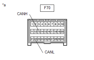
(b) Disconnect the airbag sensor assembly connector.
|
(c) Measure the resistance according to the value(s) in the table below. Standard Resistance:
|
|
| OK | .gif) |
REPLACE AIRBAG SENSOR ASSEMBLY
|
| NG | .gif) |
REPAIR OR REPLACE CAN MAIN BUS LINES OR CONNECTOR (AIRBAG SENSOR ASSEMBLY - NO. 4 CAN JUNCTION CONNECTOR) |
 Check Bus 4 Lines for Short Circuit
DESCRIPTION
There may be a short circuit between the CAN main bus lines and/or CAN branch
lines when the resistance between terminals 22 (CA2H) and 7 (CA2L) of the central
gateway ECU (network ga ...
 Check Bus 4 Line for Short to +B
DESCRIPTION
There may be a short circuit between one of the CAN bus lines and +B when no
resistance exists between terminal 22 (CA2H) of the central gateway ECU (network
gateway ECU) and terminal ...
Other materials:
Toyota CH-R Service Manual > 3zr-fae Oil And Oil Filter: Replacement
REPLACEMENT
CAUTION / NOTICE / HINT
CAUTION:
Prolonged and repeated contact with engine oil will result in the removal
of natural oils from the skin, leading to dryness, irritation and dermatitis.
In addition, used engine oil contains potentially harmful contaminants which
may ...
Toyota CH-R Service Manual > Automatic High Beam System: Automatic High Beam System (B124B)
DESCRIPTION
This DTC is stored when the main body ECU (multiplex network body ECU) detects
malfunctions in the automatic high beam system.
DTC No.
Detection Item
DTC Detection Condition
Trouble Area
B124B
Automatic High Beam ...
Toyota C-HR (AX20) 2023-2026 Owner's Manual
Toyota CH-R Owners Manual
- For safety and security
- Instrument cluster
- Operation of each component
- Driving
- Interior features
- Maintenance and care
- When trouble arises
- Vehicle specifications
- For owners
Toyota CH-R Service Manual
- Introduction
- Maintenance
- Audio / Video
- Cellular Communication
- Navigation / Multi Info Display
- Park Assist / Monitoring
- Brake (front)
- Brake (rear)
- Brake Control / Dynamic Control Systems
- Brake System (other)
- Parking Brake
- Axle And Differential
- Drive Shaft / Propeller Shaft
- K114 Cvt
- 3zr-fae Battery / Charging
- Networking
- Power Distribution
- Power Assist Systems
- Steering Column
- Steering Gear / Linkage
- Alignment / Handling Diagnosis
- Front Suspension
- Rear Suspension
- Tire / Wheel
- Tire Pressure Monitoring
- Door / Hatch
- Exterior Panels / Trim
- Horn
- Lighting (ext)
- Mirror (ext)
- Window / Glass
- Wiper / Washer
- Door Lock
- Heating / Air Conditioning
- Interior Panels / Trim
- Lighting (int)
- Meter / Gauge / Display
- Mirror (int)
- Power Outlets (int)
- Pre-collision
- Seat
- Seat Belt
- Supplemental Restraint Systems
- Theft Deterrent / Keyless Entry
0.0123

.gif)
