
Toyota CH-R Service Manual: Disassembly
DISASSEMBLY
CAUTION / NOTICE / HINT
NOTICE:
- If the rear disc brake cylinder assembly has been disassembled, perform
air bleeding for the rear disc brake cylinder.
Click here
.gif)
- Make sure not to scratch, damage or apply excessive force to any of the internal components of the rear disc brake cylinder LH.
- To prevent rusting on the inside of the rear disc brake cylinder LH, perform the rear disc brake piston removal and installation quickly.
- Do not clean the interior of the rear disc brake cylinder LH with brake cleaner.
- Do not remove any parts unless specifically instructed to do so, and only remove the parts indicated.
- When disassembling the rear disc brake cylinder LH, make sure to enter
pad replacement mode.
Click here
PROCEDURE
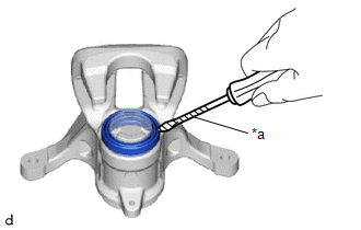
1. REMOVE CYLINDER BOOT
|
(a) Using a thin-bladed screwdriver with its tip wrapped in protective tape, remove the cylinder boot from the rear disc brake cylinder LH. NOTICE: Make sure not to scratch or damage the inside of the rear disc brake cylinder LH or the cylinder boot installation groove. |
|
2. REMOVE REAR DISC BRAKE PISTON
|
(a) To prevent scratches or other damage, insert a piece of cloth, etc., between the rear disc brake piston and the rear disc brake cylinder. |
|
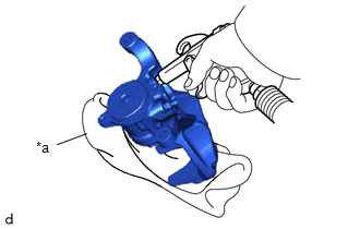
(b) Using compressed air, gradually blow in air to remove the rear disc brake piston from the rear disc brake cylinder.
CAUTION:
- Do not hold the rear disc brake cylinder with any part of your hand between the rear disc brake cylinder and rear disc brake piston.
- Do not place any part of your hand in front of the rear disc brake piston when using compressed air as a severe injury may result.
.png)
NOTICE:
Do not allow any brake fluid to spatter.
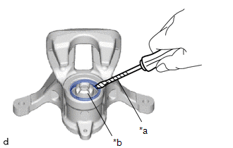
3. REMOVE PISTON SEAL
|
(a) Using a screwdriver with its tip wrapped with protective tape, remove the piston seal from the rear disc brake cylinder. NOTICE:
|
|
4. REMOVE REAR DISC BRAKE BLEEDER PLUG CAP
(a) Remove the rear disc brake bleeder plug cap from the rear disc brake bleeder plug.
5. REMOVE REAR DISC BRAKE BLEEDER PLUG
(a) Remove the rear disc brake bleeder plug from the rear disc brake cylinder assembly.
 Removal
REMOVAL
CAUTION / NOTICE / HINT
HINT:
Use the same procedure for the RH side and LH side.
The following procedure is for the LH side.
PROCEDURE
1. PRECAUTION
Click here
2. ...
 Inspection
INSPECTION
PROCEDURE
1. INSPECT PAD LINING THICKNESS
(a) Using a ruler, measure the rear disc brake pad lining thickness.
Standard Thickness:
9.5 mm (0.374 in.)
Minimum Thickne ...
Other materials:
Toyota CH-R Service Manual > Seat Belt Warning System(w/ Occupant Classification System): Terminals Of Ecu
TERMINALS OF ECU
CHECK MAIN BODY ECU (MULTIPLEX NETWORK BODY ECU) AND INSTRUMENT PANEL JUNCTION
BLOCK ASSEMBLY
*A
Main Body ECU (Multiplex Network Body ECU) with 1 Connector
-
-
*A
Main Body ECU (Multiplex Network Bo ...
Toyota CH-R Service Manual > Rear Center Seat Outer Belt Assembly: Inspection
INSPECTION
PROCEDURE
1. INSPECT REAR CENTER SEAT OUTER BELT ASSEMBLY
(a) Before installing the rear center seat outer belt assembly, check
the ELR function.
NOTICE:
Do not disassemble the retractor.
(1) When the inclination of the retractor is between 0° and 20°, check
...
Toyota C-HR (AX20) 2023-2026 Owner's Manual
Toyota CH-R Owners Manual
- For safety and security
- Instrument cluster
- Operation of each component
- Driving
- Interior features
- Maintenance and care
- When trouble arises
- Vehicle specifications
- For owners
Toyota CH-R Service Manual
- Introduction
- Maintenance
- Audio / Video
- Cellular Communication
- Navigation / Multi Info Display
- Park Assist / Monitoring
- Brake (front)
- Brake (rear)
- Brake Control / Dynamic Control Systems
- Brake System (other)
- Parking Brake
- Axle And Differential
- Drive Shaft / Propeller Shaft
- K114 Cvt
- 3zr-fae Battery / Charging
- Networking
- Power Distribution
- Power Assist Systems
- Steering Column
- Steering Gear / Linkage
- Alignment / Handling Diagnosis
- Front Suspension
- Rear Suspension
- Tire / Wheel
- Tire Pressure Monitoring
- Door / Hatch
- Exterior Panels / Trim
- Horn
- Lighting (ext)
- Mirror (ext)
- Window / Glass
- Wiper / Washer
- Door Lock
- Heating / Air Conditioning
- Interior Panels / Trim
- Lighting (int)
- Meter / Gauge / Display
- Mirror (int)
- Power Outlets (int)
- Pre-collision
- Seat
- Seat Belt
- Supplemental Restraint Systems
- Theft Deterrent / Keyless Entry

0.0081