Toyota CH-R Service Manual: Installation
INSTALLATION
CAUTION / NOTICE / HINT
CAUTION:
- Be sure to read Precaution thoroughly before servicing.
.png)
Click here
.gif)
- Wear protective gloves. Sharp areas on the parts may injure your hands.
HINT:
- Use the same procedure for the driver side and front passenger side.
- The procedure listed below is for the driver side.
PROCEDURE
1. INSTALL FRONT SEAT ASSEMBLY
|
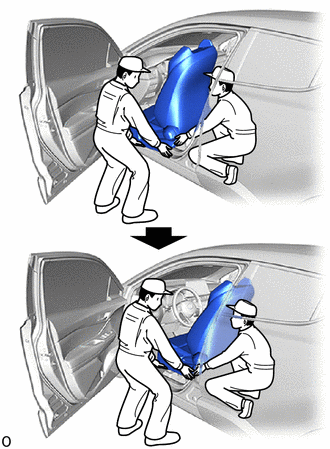
(a) Place the front seat assembly in the vehicle as shown in the illustration. NOTICE:
|
|
(b) Connect the front seat airbag assembly connector under the front seat assembly.
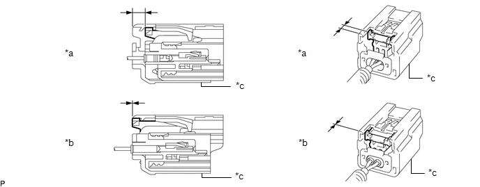
(1) Before connecting the connector, check that the position of the housing lock is correct as shown in the illustration.
|
*a |
Correct |
*b |
Incorrect |
|
*c |
Yellow CPA |
- |
- |
(2) Be sure to engage the connectors until they are locked (when locking, make sure that a click sound can be heard).
NOTICE:
- When connecting any airbag connector, take care not to damage the airbag wire harness.
- When engaged, the white housing lock will slide. Be sure not to hold the white housing lock and upper part of the yellow CPA, as it may result in an insecure fit.
(c) Connect the front seat cushion airbag assembly connector. (for Front Passenger Side)
(d) Connect each connector and engage each clamp under the front seat assembly.
(e) Temporarily install the front seat assembly with the 4 bolts.
(f) Operate the seat track adjusting handle and move the front seat assembly to the rearmost position.
|
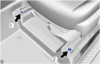
(g) Using a T50 "TORX" socket wrench, tighten the 2 bolts on the front side of the front seat assembly. Torque: 37 N·m {377 kgf·cm, 27 ft·lbf} NOTICE: Tighten the bolts in the order shown in the illustration. |
|
(h) Operate the seat track adjusting handle and move the front seat assembly to the foremost position.
|
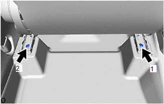
(i) Using a T50 "TORX" socket wrench, tighten the 2 bolts on the rear side of the front seat assembly. Torque: 37 N·m {377 kgf·cm, 27 ft·lbf} NOTICE: Tighten the bolts in the order shown in the illustration. |
|
2. INSPECT SEAT SLIDE ADJUSTER LOCK
(a) While performing a sliding operation of the front seat assembly, check that the left and right adjusters move together smoothly and lock simultaneously. If the seat adjusters do not lock simultaneously, loosen the front seat assembly installation bolts and adjust the adjuster position.
3. INSTALL INNER SEAT TRACK BRACKET COVER
(a) Operate the seat track adjusting handle and move the front seat assembly to the foremost position.
|
(b) Engage the claws and guide to install the inner seat track bracket cover. |
|
.png)
4. INSTALL OUTER SEAT TRACK COVER
|
(a) Engage the claws and guide to install the outer seat track cover. |
|
.png)
5. INSTALL FRONT INNER SEAT TRACK BRACKET COVER
(a) Operate the seat track adjusting handle and move the front seat assembly to the rearmost position.
|
(b) Engage the claws to install the front inner seat track bracket cover. |
|
.png)
6. INSTALL FRONT OUTER SEAT TRACK BRACKET COVER
|
(a) Engage the claws to install the front outer seat track bracket cover. |
|
.png)
7. INSTALL FRONT SEAT HEADREST ASSEMBLY
(a) Install the front seat headrest assembly to the front seat assembly.
8. CONNECT CABLE TO NEGATIVE BATTERY TERMINAL
Click here
NOTICE:
When disconnecting the cable, some systems need to be initialized after the cable is reconnected.
Click here
9. CHECK SEAT HEATER (w/ Seat Heater System)
Click here
10. PERFORM DIAGNOSTIC SYSTEM CHECK
Click here
11. INSPECT SRS WARNING LIGHT
Click here
 Removal
REMOVAL
CAUTION / NOTICE / HINT
The necessary procedures (adjustment, calibration, initialization, or registration)
that must be performed after parts are removed, installed, or replaced during th ...

Other materials:
Toyota CH-R Service Manual > Lighting System: Door Unlock Detection Switch Circuit
DESCRIPTION
The main body ECU (multiplex network body ECU) detects the condition of each
door unlock detection switch.
WIRING DIAGRAM
CAUTION / NOTICE / HINT
NOTICE:
Before replacing the main body ECU (multiplex network body ECU), refer to Registration*1.
Click here
*1: w/ Smart ...
Toyota CH-R Service Manual > Lighting System: High Beam Headlight Circuit
DESCRIPTION
The main body ECU (multiplex network body ECU) controls the high beam headlights.
WIRING DIAGRAM
CAUTION / NOTICE / HINT
NOTICE:
Inspect the fuse for circuits related to this system before performing
the following procedure.
Check the operation of the low beam head ...
Toyota C-HR (AX20) 2023-2026 Owner's Manual
Toyota CH-R Owners Manual
- For safety and security
- Instrument cluster
- Operation of each component
- Driving
- Interior features
- Maintenance and care
- When trouble arises
- Vehicle specifications
- For owners
Toyota CH-R Service Manual
- Introduction
- Maintenance
- Audio / Video
- Cellular Communication
- Navigation / Multi Info Display
- Park Assist / Monitoring
- Brake (front)
- Brake (rear)
- Brake Control / Dynamic Control Systems
- Brake System (other)
- Parking Brake
- Axle And Differential
- Drive Shaft / Propeller Shaft
- K114 Cvt
- 3zr-fae Battery / Charging
- Networking
- Power Distribution
- Power Assist Systems
- Steering Column
- Steering Gear / Linkage
- Alignment / Handling Diagnosis
- Front Suspension
- Rear Suspension
- Tire / Wheel
- Tire Pressure Monitoring
- Door / Hatch
- Exterior Panels / Trim
- Horn
- Lighting (ext)
- Mirror (ext)
- Window / Glass
- Wiper / Washer
- Door Lock
- Heating / Air Conditioning
- Interior Panels / Trim
- Lighting (int)
- Meter / Gauge / Display
- Mirror (int)
- Power Outlets (int)
- Pre-collision
- Seat
- Seat Belt
- Supplemental Restraint Systems
- Theft Deterrent / Keyless Entry

0.008