Toyota CH-R Service Manual: Clock
Components
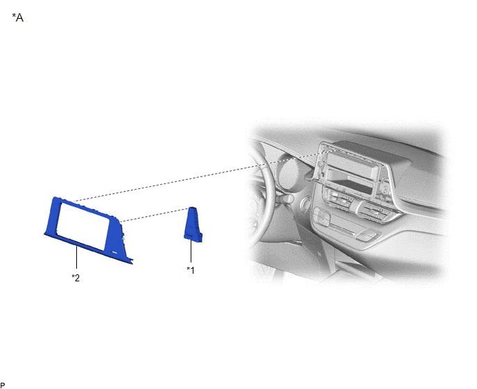
COMPONENTS
ILLUSTRATION
|
*A |
w/o Display |
- |
- |
|
*1 |
CLOCK ASSEMBLY |
*2 |
INSTRUMENT CLUSTER FINISH CENTER PANEL SUB-ASSEMBLY |
ILLUSTRATION
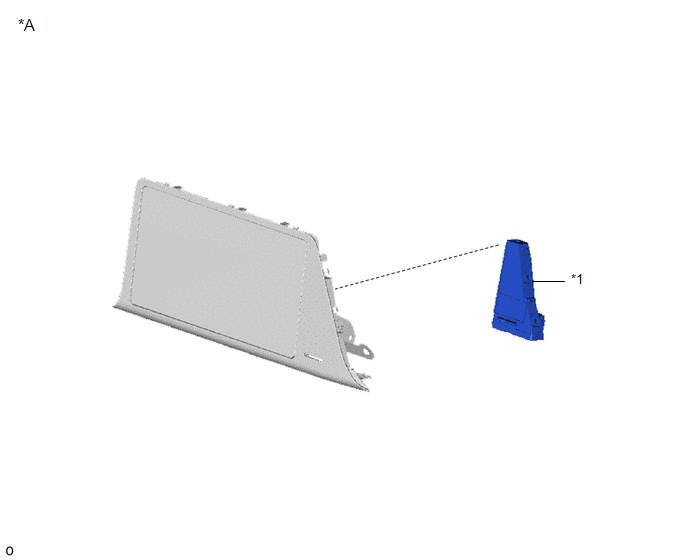
|
*A |
w/ Display |
- |
- |
|
*1 |
CLOCK ASSEMBLY |
- |
- |
Removal
REMOVAL
PROCEDURE
1. REMOVE INSTRUMENT CLUSTER FINISH CENTER PANEL SUB-ASSEMBLY (w/o Display)
Click here .gif)
2. REMOVE RADIO AND DISPLAY RECEIVER ASSEMBLY WITH BRACKET (w/ Display)
Click here
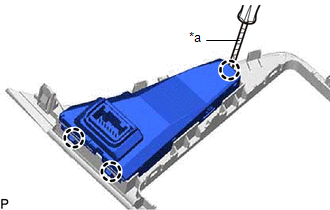
3. REMOVE CLOCK ASSEMBLY
|
(a) Using a screwdriver with its tip wrapped in protective tape, disengage the claws to remove the clock assembly. |
|
Installation
INSTALLATION
PROCEDURE
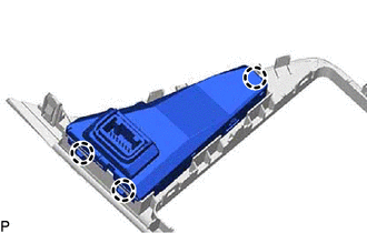
1. INSTALL CLOCK ASSEMBLY
|
(a) Engage the claws to install the clock assembly. |
|
2. INSTALL INSTRUMENT CLUSTER FINISH CENTER PANEL SUB-ASSEMBLY (w/o Display)
Click here .gif)
3. INSTALL RADIO AND DISPLAY RECEIVER ASSEMBLY WITH BRACKET (w/ Display)
Click here

 Clock System
...
Other materials:
Toyota CH-R Service Manual > Maintenance: Air Conditioning Filter(for Valeo Made)
Components
COMPONENTS
ILLUSTRATION
*1
AIR FILTER COVER PLATE
*2
CLEAN AIR FILTER
*3
GLOVE COMPARTMENT DOOR ASSEMBLY
-
-
Removal
REMOVAL
PROCEDURE
1. REMOVE GLOVE COMPARTMENT DOOR ASSEM ...
Toyota CH-R Service Manual > Front Seat Side Airbag Assembly: On-vehicle Inspection
ON-VEHICLE INSPECTION
CAUTION / NOTICE / HINT
CAUTION:
Be sure to correctly follow the removal and installation procedures for the front
seat airbag assemblies.
PROCEDURE
1. INSPECT FRONT SEAT AIRBAG ASSEMBLY (for Vehicle not Involved in Collision)
(a) Perform a diagnostic system check.
Cli ...
Toyota C-HR (AX20) 2023-2026 Owner's Manual
Toyota CH-R Owners Manual
- For safety and security
- Instrument cluster
- Operation of each component
- Driving
- Interior features
- Maintenance and care
- When trouble arises
- Vehicle specifications
- For owners
Toyota CH-R Service Manual
- Introduction
- Maintenance
- Audio / Video
- Cellular Communication
- Navigation / Multi Info Display
- Park Assist / Monitoring
- Brake (front)
- Brake (rear)
- Brake Control / Dynamic Control Systems
- Brake System (other)
- Parking Brake
- Axle And Differential
- Drive Shaft / Propeller Shaft
- K114 Cvt
- 3zr-fae Battery / Charging
- Networking
- Power Distribution
- Power Assist Systems
- Steering Column
- Steering Gear / Linkage
- Alignment / Handling Diagnosis
- Front Suspension
- Rear Suspension
- Tire / Wheel
- Tire Pressure Monitoring
- Door / Hatch
- Exterior Panels / Trim
- Horn
- Lighting (ext)
- Mirror (ext)
- Window / Glass
- Wiper / Washer
- Door Lock
- Heating / Air Conditioning
- Interior Panels / Trim
- Lighting (int)
- Meter / Gauge / Display
- Mirror (int)
- Power Outlets (int)
- Pre-collision
- Seat
- Seat Belt
- Supplemental Restraint Systems
- Theft Deterrent / Keyless Entry

0.0083