Toyota CH-R Service Manual: Disassembly
DISASSEMBLY
PROCEDURE
1. REMOVE NO. 1 POWER OUTLET SOCKET ASSEMBLY
Click here .gif)
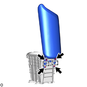
2. REMOVE NO. 1 POWER OUTLET SOCKET COVER
Click here
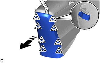
3. REMOVE CONSOLE REAR END PANEL
(a) Using a moulding remover A, disengage the clips to remove the console rear end panel as shown in the illustration.
.png) |
Remove in this Direction |
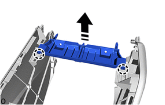
4. REMOVE CONSOLE BOX RETAINER
(a) Disengage the claws to remove the console box retainer as shown in the illustration.
|
|
Remove in this Direction |
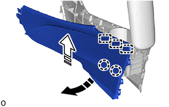
5. REMOVE NO. 1 BOX SIDE PANEL
(a) Disengage the claws and guides to remove the No. 1 box side panel as shown in the illustration.
|
|
Remove in this Direction (1) |
.png) |
Remove in this Direction (2) |
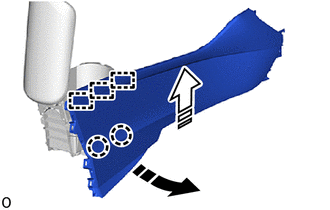
6. REMOVE NO. 2 BOX SIDE PANEL
(a) Disengage the claws and guides to remove the No. 2 box side panel as shown in the illustration.
|
|
Remove in this Direction (1) |
|
|
Remove in this Direction (2) |
7. REMOVE CONSOLE COMPARTMENT DOOR SUB-ASSEMBLY
|
(a) Remove the 4 screws. |
|
(b) Disengage the guides to remove the console compartment door sub-assembly.
 Components
COMPONENTS
ILLUSTRATION
*1
COWL SIDE TRIM BOARD LH
*2
FRONT DOOR SCUFF PLATE LH
*3
INSTRUMENT CLUSTER FINISH PANEL GARNISH A ...
 Removal
REMOVAL
PROCEDURE
1. REMOVE FRONT DOOR SCUFF PLATE LH
(a) Disengage the claws and guides to remove the front door scuff plate LH as
shown in the illustration.
Place Hands H ...
Other materials:
Toyota CH-R Service Manual > Occupant Classification System: Yaw Rate Sensor Module Malfunction (B1798,B1799)
DESCRIPTION
The occupant detection ECU receives signals from the acceleration sensor (airbag
sensor assembly) and skid control ECU via CAN communication.
DTC No.
Detection Item
DTC Detection Condition
Trouble Area
B1798
Yaw ...
Toyota CH-R Service Manual > Steering Gear: Disassembly
DISASSEMBLY
PROCEDURE
1. REMOVE STEERING RACK BOOT CLIP (for LH Side)
(a) Using pliers, remove the steering rack boot clip.
2. REMOVE STEERING RACK BOOT CLIP (for RH Side)
HINT:
Perform the same procedure as for the LH side.
3. REMOVE STEERING RACK BOOT CLAMP (for LH Side)
(a) Usi ...
Toyota C-HR (AX20) 2023-2026 Owner's Manual
Toyota CH-R Owners Manual
- For safety and security
- Instrument cluster
- Operation of each component
- Driving
- Interior features
- Maintenance and care
- When trouble arises
- Vehicle specifications
- For owners
Toyota CH-R Service Manual
- Introduction
- Maintenance
- Audio / Video
- Cellular Communication
- Navigation / Multi Info Display
- Park Assist / Monitoring
- Brake (front)
- Brake (rear)
- Brake Control / Dynamic Control Systems
- Brake System (other)
- Parking Brake
- Axle And Differential
- Drive Shaft / Propeller Shaft
- K114 Cvt
- 3zr-fae Battery / Charging
- Networking
- Power Distribution
- Power Assist Systems
- Steering Column
- Steering Gear / Linkage
- Alignment / Handling Diagnosis
- Front Suspension
- Rear Suspension
- Tire / Wheel
- Tire Pressure Monitoring
- Door / Hatch
- Exterior Panels / Trim
- Horn
- Lighting (ext)
- Mirror (ext)
- Window / Glass
- Wiper / Washer
- Door Lock
- Heating / Air Conditioning
- Interior Panels / Trim
- Lighting (int)
- Meter / Gauge / Display
- Mirror (int)
- Power Outlets (int)
- Pre-collision
- Seat
- Seat Belt
- Supplemental Restraint Systems
- Theft Deterrent / Keyless Entry

0.0087