Toyota CH-R Service Manual: Pressure Sensor Circuit (B1423)
DESCRIPTION
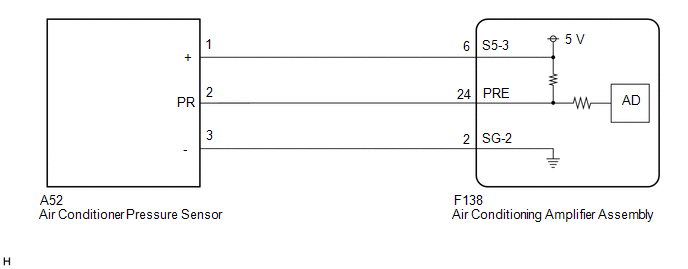
This DTC is stored if refrigerant pressure on the high pressure side is extremely low (195 kPa (2.0 kgf/cm2, 28 psi) or less) or extremely high (2812 kPa (28.7 kgf/cm2, 408 psi) or more). The air conditioner pressure (2 words) sensor, which is installed to the high pressure side pipe to detect refrigerant pressure, sends a refrigerant pressure signal to the air conditioning amplifier assembly. The air conditioning conditioner pressure (2 words) converts this signal to a pressure value according to the sensor characteristics and uses it to control the compressor.
|
DTC No. |
Detection Item |
DTC Detection Condition |
Trouble Area |
Memory |
|---|---|---|---|---|
|
B1423 |
Pressure Sensor Circuit |
|
|
- |
|
Vehicle Condition |
|||||
|---|---|---|---|---|---|
|
Pattern 1 |
Pattern 2 |
Pattern 3 |
Pattern 4 |
||
|
Diagnosis Condition |
Ignition switch ON |
○ |
○ |
○ |
○ |
|
Malfunction Status |
Open in air conditioner pressure sensor circuit |
○ |
- |
- |
- |
|
Short in air conditioner pressure sensor circuit |
- |
○ |
- |
- |
|
|
Refrigerant pressure on high pressure side is extremely low (195 kPa (2.0 kgf/cm2, 28 psi) or less) |
- |
- |
○ |
- |
|
|
Refrigerant pressure on high pressure side is extremely high (2812 kPa (28.7 kgf/cm2, 408 psi) or more) |
- |
- |
- |
○ |
|
|
Detection Time |
4 seconds or more |
4 seconds or more |
4 seconds or more |
4 seconds or more |
|
|
Number of Trips |
1 trip |
1 trip |
1 trip |
1 trip |
|
WIRING DIAGRAM
CAUTION / NOTICE / HINT
HINT:
If DTC B1423/23 and B14B8 are output at the same time, troubleshoot for DTC B14B8 first.
Click here
.gif)
PROCEDURE
|
1. |
CHECK FOR DTC |
(a) Check for DTCs.
Click here
|
Result |
Proceed to |
|---|---|
|
DTC B14B8 is output |
A |
|
DTC B14B8 is not output |
B |
| A | .gif) |
GO TO DTC B14B8 |
|
.gif)
|
2. |
CHECK REFRIGERANT SHORTAGE |
(a) Prepare the vehicle according to the table below.
Measurement Condition:|
Item |
Condition |
|---|---|
|
A/C switch |
On |
|
Ambient temperature* |
0 to 49°C (32 to 120°F) |
|
Blower speed |
HI |
*: If the ambient temperature is not within the range shown, do not perform this check.
(b) Connect the Techstream to the DLC3.
(c) Turn the ignition switch to ON.
(d) Turn the Techstream on.
(e) Enter the following menus: Body Electrical / Air Conditioner / Utility / Refrigerant Gas Volume Check.
Body Electrical > Air Conditioner > Utility|
Tester Display |
|---|
|
Refrigerant Gas Volume Check |
|
Result |
Amount of Refrigerant |
|---|---|
|
Refrigerant shortage |
Insufficient or leakage |
|
Refrigerant correct |
Correct |
|
Result |
Proceed to |
|---|---|
|
Insufficient or leakage |
A |
|
Correct |
B |
| B | |
GO TO STEP 4 |
|
|
3. |
REPAIR AIR CONDITIONING SYSTEM LEAK |
(a) Identify the area where refrigerant leaks from.
Click here
(b) Repair the identified area of the air conditioning system.
(c) Evacuate the air conditioning system.
| NEXT | |
CHARGE SYSTEM WITH REFRIGERANT |
|
4. |
CHECK REFRIGERANT PRESSURE |
(a) Connect the Techstream to the DLC3.
(b) Turn the ignition switch to ON.
(c) Turn the Techstream on.
(d) Enter the following menus: Body Electrical / Air Conditioner / Data List.
(e) Read the Data List according to the display on the Techstream.
Body Electrical > Air Conditioner > Data List|
Tester Display |
Measurement Item |
Range |
Normal Condition |
Diagnostic Note |
|---|---|---|---|---|
|
Regulator Pressure Sensor |
Air conditioner pressure sensor |
Min.: -456.6 kPaG Max.: 3294.3 kPaG |
Actual refrigerant pressure displayed |
- |
|
Tester Display |
|---|
|
Regulator Pressure Sensor |
(f) Install a manifold gauge set.
Click here
(g) Read the manifold gauge pressure when the following conditions are met.
(1) Prepare the vehicle according to the table below.
Measurement Condition:|
Item |
Condition |
|---|---|
|
Vehicle doors |
Fully open |
|
Temperature setting |
MAX COLD |
|
Blower speed |
HI |
|
A/C switch |
On |
|
Recirculation/fresh switch |
RECIRCULATION |
|
Interior temperature |
25 to 35°C (77 to 95°F) |
Standard Pressure:
Low pressure side
150 to 250 kPa (1.5 to 2.5 kgf/cm2, 22 to 36 psi)
High pressure side
1370 to 1570 kPa (14 to 16 kgf/cm2, 199 to 228 psi)
(h) Compare the values displayed in the Data List and on the manifold gauge.
OK:
The values displayed in the Data List and on the manifold gauge match.
| OK | |
CHARGE SYSTEM WITH REFRIGERANT |
|
|
5. |
CHECK HARNESS AND CONNECTOR (POWER SOURCE CIRCUIT) |
|
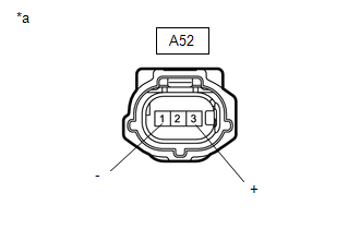
(a) Disconnect the air conditioner pressure sensor connector. |
|
(b) Measure the voltage according to the value(s) in the table below.
Standard Voltage:
|
Tester Connection |
Switch Condition |
Specified Condition |
|---|---|---|
|
A52-3 (+) - A52-1 (-) |
Ignition switch ON |
4.75 to 5.25 V |
| NG | |
GO TO STEP 10 |
|
|
6. |
CHECK HARNESS AND CONNECTOR (AIR CONDITIONER PRESSURE SENSOR - BODY GROUND) |
(a) Measure the resistance according to the value(s) in the table below.
Standard Resistance:
|
Tester Connection |
Condition |
Specified Condition |
|---|---|---|
|
A52-1 (-) - Body ground |
Always |
Below 1 Ω |
| NG | |
GO TO STEP 9 |
|
|
7. |
CHECK HARNESS AND CONNECTOR (AIR CONDITIONING AMPLIFIER ASSEMBLY - AIR CONDITIONER PRESSURE SENSOR) |
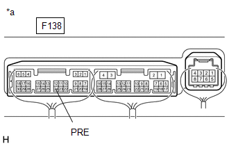
(a) Disconnect the F138 air conditioning amplifier assembly connector.
(b) Measure the resistance according to the value(s) in the table below.
Standard Resistance:
|
Tester Connection |
Condition |
Specified Condition |
|---|---|---|
|
A52-2 (PR) - F138-24 (PRE) |
Always |
Below 1 Ω |
|
A52-2 (PR) or F138-24 (PRE) - Body ground |
Always |
10 kΩ or higher |
| NG | |
REPAIR OR REPLACE HARNESS OR CONNECTOR |
|
|
8. |
INSPECT AIR CONDITIONER PRESSURE SENSOR (SENSOR SIGNAL CIRCUIT) |
(a) Measure the voltage when the following conditions are met.
Measurement Condition:|
Item |
Condition |
|---|---|
|
Vehicle doors |
Fully open |
|
Temperature setting |
MAX COLD |
|
Blower speed |
HI |
|
A/C switch |
On |
|
Recirculation/fresh switch |
RECIRCULATION |
|
Interior temperature |
25 to 35°C (77 to 95°F) |
NOTICE:
- If refrigerant pressure on the high pressure side becomes extremely high during the inspection (if the voltage exceeds 4.61 V), the fail-safe function stops compressor operation. Therefore, measure the voltage before the fail-safe operation.
- It is necessary to measure the voltage for a certain amount of time (approximately 10 minutes) because the malfunction may recur after a while.
HINT:
When the outside air temperature is low (below -1.5°C (29.3°F)), the compressor stops due to operation of the thermistor assembly and the No. 1 cooler thermistor (evaporator temperature sensor) to prevent the evaporator from freezing. In this case, perform the inspection in a warm indoor environment.
|
(1) Measure the voltage according to the value(s) in the table below. Standard Voltage:
|
|
(b) Connect the Techstream to the DLC3.
(c) Turn the ignition switch to ON.
(d) Turn the Techstream on.
(e) Enter the following menus: Body Electrical / Air Conditioner / Data List.
(f) Read the Data List according to the display on the Techstream.
Body Electrical > Air Conditioner > Data List|
Tester Display |
Measurement Item |
Range |
Normal Condition |
Diagnostic Note |
|---|---|---|---|---|
|
Regulator Pressure Sensor |
Air conditioner pressure sensor |
Min.: -456.6 kPaG Max.: 3294.3 kPaG |
Actual refrigerant pressure displayed |
- |
|
Tester Display |
|---|
|
Regulator Pressure Sensor |
OK:
The voltage and value displayed in the Data List change.
|
Result |
Proceed to |
|---|---|
|
OK |
A |
|
NG (The voltage changes but the value displayed in the Data List does not change.) |
|
|
NG (The voltage does not change.) |
B |
| A | |
REPLACE AIR CONDITIONING AMPLIFIER ASSEMBLY |
| B | |
REPLACE AIR CONDITIONER PRESSURE SENSOR |
|
9. |
CHECK HARNESS AND CONNECTOR (AIR CONDITIONING AMPLIFIER ASSEMBLY - AIR CONDITIONER PRESSURE SENSOR) |
(a) Disconnect the F138 air conditioning amplifier assembly connector.
(b) Measure the resistance according to the value(s) in the table below.
Standard Resistance:
|
Tester Connection |
Condition |
Specified Condition |
|---|---|---|
|
A52-1 (-) - F138-2 (SG-2) |
Always |
Below 1 Ω |
|
A52-1 (-) or F138-2 (SG-2) - Body ground |
Always |
10 kΩ or higher |
| OK | |
REPLACE AIR CONDITIONING AMPLIFIER ASSEMBLY |
| NG | |
REPAIR OR REPLACE HARNESS OR CONNECTOR |
|
10. |
CHECK HARNESS AND CONNECTOR (AIR CONDITIONING AMPLIFIER ASSEMBLY - AIR CONDITIONER PRESSURE SENSOR) |
(a) Disconnect the F138 air conditioning amplifier assembly connector.
(b) Measure the resistance according to the value(s) in the table below.
Standard Resistance:
|
Tester Connection |
Condition |
Specified Condition |
|---|---|---|
|
A52-3 (+) - F138-6 (S5-3) |
Always |
Below 1 Ω |
|
A52-3 (+) or F138-6 (S5-3) - Body ground |
Always |
10 kΩ or higher |
| OK | |
REPLACE AIR CONDITIONING AMPLIFIER ASSEMBLY |
| NG | |
REPAIR OR REPLACE HARNESS OR CONNECTOR |
 Evaporator Temperature Sensor Circuit (B1413)
DESCRIPTION
The No. 1 cooler thermistor (evaporator temperature sensor) is installed to the
evaporator in the air conditioner unit to detect the temperature of the cooled air
that has passed thro ...
 Room Temperature Sensor Circuit (B1411)
DESCRIPTION
The cooler thermistor (room temperature sensor) is installed in the instrument
panel to detect the cabin temperature, which is used to control the air conditioning
system. The resista ...
Other materials:
Toyota CH-R Service Manual > Blower Unit(for Denso Made): Reassembly
REASSEMBLY
PROCEDURE
1. INSTALL NO. 1 BLOWER DAMPER SERVO SUB-ASSEMBLY
(a) Connect the 2 links of the blower assembly to the 2 plates of the
No. 1 blower damper servo sub-assembly as shown in the illustration.
...
Toyota CH-R Service Manual > Continuously Variable Transaxle System: Mechanical System Tests
MECHANICAL SYSTEM TESTS
SHIFT TIME LAG TEST
NOTICE:
This test must be conducted after checking and confirming that the engine
is operating normally.
Perform this test while the CVT fluid temperature is between 50 and
100°C (122 and 212°F).
Perform this test with the A/C ...
Toyota C-HR (AX20) 2023-2026 Owner's Manual
Toyota CH-R Owners Manual
- For safety and security
- Instrument cluster
- Operation of each component
- Driving
- Interior features
- Maintenance and care
- When trouble arises
- Vehicle specifications
- For owners
Toyota CH-R Service Manual
- Introduction
- Maintenance
- Audio / Video
- Cellular Communication
- Navigation / Multi Info Display
- Park Assist / Monitoring
- Brake (front)
- Brake (rear)
- Brake Control / Dynamic Control Systems
- Brake System (other)
- Parking Brake
- Axle And Differential
- Drive Shaft / Propeller Shaft
- K114 Cvt
- 3zr-fae Battery / Charging
- Networking
- Power Distribution
- Power Assist Systems
- Steering Column
- Steering Gear / Linkage
- Alignment / Handling Diagnosis
- Front Suspension
- Rear Suspension
- Tire / Wheel
- Tire Pressure Monitoring
- Door / Hatch
- Exterior Panels / Trim
- Horn
- Lighting (ext)
- Mirror (ext)
- Window / Glass
- Wiper / Washer
- Door Lock
- Heating / Air Conditioning
- Interior Panels / Trim
- Lighting (int)
- Meter / Gauge / Display
- Mirror (int)
- Power Outlets (int)
- Pre-collision
- Seat
- Seat Belt
- Supplemental Restraint Systems
- Theft Deterrent / Keyless Entry

0.0087