Toyota CH-R Service Manual: Parts Location
PARTS LOCATION
ILLUSTRATION
|
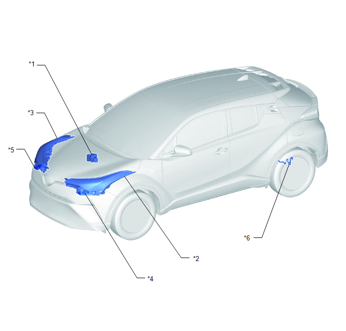
*1 |
BRAKE ACTUATOR ASSEMBLY (SKID CONTROL ECU) |
*2 |
HEADLIGHT UNIT ASSEMBLY LH - HEADLIGHT LEVELING MOTOR |
|
*3 |
HEADLIGHT UNIT ASSEMBLY RH - HEADLIGHT LEVELING MOTOR |
*4 |
HEADLIGHT ECU SUB-ASSEMBLY LH |
|
*5 |
HEADLIGHT ECU SUB-ASSEMBLY RH |
*6 |
REAR HEIGHT CONTROL SENSOR SUB-ASSEMBLY LH |
ILLUSTRATION
|
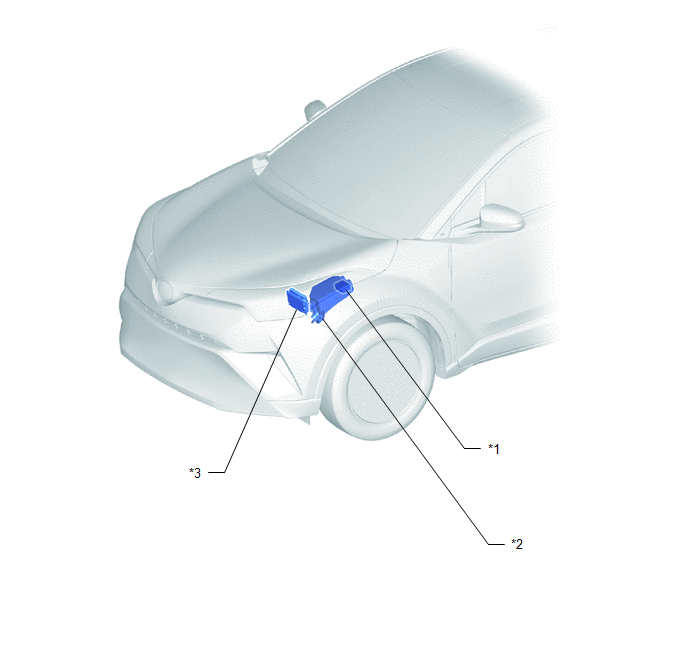
*1 |
NO. 1 ENGINE ROOM RELAY BLOCK |
*2 |
NO. 1 INTEGRATION RELAY - H-LP LH RELAY - H-LP RH RELAY |
|
*3 |
ECM |
- |
- |
ILLUSTRATION
|
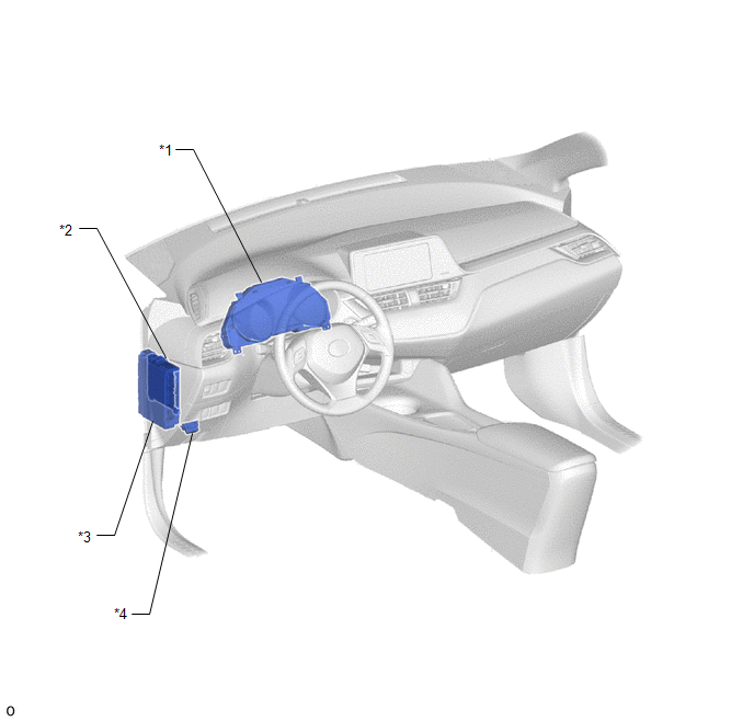
*1 |
COMBINATION METER ASSEMBLY |
*2 |
MAIN BODY ECU (MULTIPLEX NETWORK BODY ECU) |
|
*3 |
INSTRUMENT PANEL JUNCTION BLOCK ASSEMBLY - ECU-IG1 NO. 3 FUSE |
*4 |
DLC3 |
 Precaution
PRECAUTION
IGNITION SWITCH EXPRESSIONS
(a) The type of ignition switch used on this model differs depending on the specifications
of the vehicle. The expressions listed in the table below are used ...
 System Diagram
SYSTEM DIAGRAM
HEADLIGHT ASSEMBLY
...
Other materials:
Toyota CH-R Service Manual > Blind Spot Monitor System: Short to +B in Outer Mirror Indicator(Slave) (C1AB1)
DESCRIPTION
This DTC is stored when the blind spot monitor sensor RH (Slave) detects a short
to +B in the outer rear view mirror indicator RH.
DTC No.
Detection Item
DTC Detection Condition
Trouble Area
C1AB1
Short to +B in ...
Toyota CH-R Service Manual > Back Door Glass: Components
COMPONENTS
ILLUSTRATION
*A
for Upper Side
*B
for Side
*1
BACK DOOR GLASS
*2
BACK DOOR GLASS SPACER
*3
BACK WINDOW LOWER MOULDING
*4
BACK WINDOW OUTSIDE ...
Toyota C-HR (AX20) 2023-2026 Owner's Manual
Toyota CH-R Owners Manual
- For safety and security
- Instrument cluster
- Operation of each component
- Driving
- Interior features
- Maintenance and care
- When trouble arises
- Vehicle specifications
- For owners
Toyota CH-R Service Manual
- Introduction
- Maintenance
- Audio / Video
- Cellular Communication
- Navigation / Multi Info Display
- Park Assist / Monitoring
- Brake (front)
- Brake (rear)
- Brake Control / Dynamic Control Systems
- Brake System (other)
- Parking Brake
- Axle And Differential
- Drive Shaft / Propeller Shaft
- K114 Cvt
- 3zr-fae Battery / Charging
- Networking
- Power Distribution
- Power Assist Systems
- Steering Column
- Steering Gear / Linkage
- Alignment / Handling Diagnosis
- Front Suspension
- Rear Suspension
- Tire / Wheel
- Tire Pressure Monitoring
- Door / Hatch
- Exterior Panels / Trim
- Horn
- Lighting (ext)
- Mirror (ext)
- Window / Glass
- Wiper / Washer
- Door Lock
- Heating / Air Conditioning
- Interior Panels / Trim
- Lighting (int)
- Meter / Gauge / Display
- Mirror (int)
- Power Outlets (int)
- Pre-collision
- Seat
- Seat Belt
- Supplemental Restraint Systems
- Theft Deterrent / Keyless Entry

0.0073