Toyota CH-R Service Manual: Horn
Components
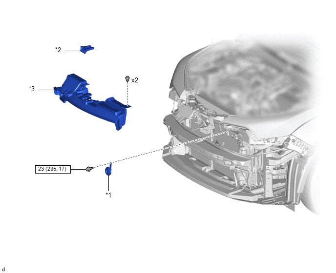
COMPONENTS
ILLUSTRATION
|
*1 |
LOW PITCHED HORN ASSEMBLY |
*2 |
NO.1 RADIATOR GRILLE RETAINER |
|
*3 |
NO.1 RADIATOR TO SUPPORT SEAL |
- |
- |
.png) |
N*m (kgf*cm, ft.*lbf): Specified torque |
- |
- |
Removal
REMOVAL
PROCEDURE
1. REMOVE FRONT BUMPER ASSEMBLY
Click here
.gif)
2. REMOVE NO.1 RADIATOR GRILLE RETAINER
Click here
3. REMOVE NO.1 RADIATOR TO SUPPORT SEAL
Click here
4. REMOVE LOW PITCHED HORN ASSEMBLY
|
(a) Disconnect the connector. |
|
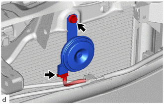
(b) Remove the bolt and low pitched horn assembly.
Inspection
INSPECTION
PROCEDURE
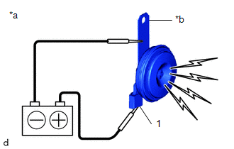
1. INSPECT LOW PITCHED HORN ASSEMBLY
(a) Check the operation.
|
(1) Apply battery voltage and check the operation of the low pitched horn assembly according to the table below. OK:
If the result is not as specified, replace the low pitched horn assembly. |
|
Installation
INSTALLATION
PROCEDURE
1. INSTALL LOW PITCHED HORN ASSEMBLY
(a) Install the low pitched horn assembly with the bolt.
Torque:
23 N·m {235 kgf·cm, 17 ft·lbf}
(b) Connect the connector.
2. INSTALL NO.1 RADIATOR TO SUPPORT SEAL
Click here
.gif)
3. INSTALL NO.1 RADIATOR GRILLE RETAINER
Click here
4. INSTALL FRONT BUMPER ASSEMBLY
Click here
 Horn
Horn
...
 Horn System
...
Other materials:
Toyota CH-R Service Manual > Charging System: Diagnostic Trouble Code Chart
DIAGNOSTIC TROUBLE CODE CHART
Charging System
DTC No.
Detection Item
Link
P161A
Lost Communication with Alternator
...
Toyota CH-R Service Manual > Knee Airbag Assembly: Disposal
DISPOSAL
CAUTION / NOTICE / HINT
CAUTION:
Before performing pre-disposal deployment of any SRS part, review and closely
follow all applicable environmental and hazardous material regulations. Pre-disposal
deployment may be considered hazardous material treatment.
PROCEDURE
1. PRECAUTION
...
Toyota C-HR (AX20) 2023-2026 Owner's Manual
Toyota CH-R Owners Manual
- For safety and security
- Instrument cluster
- Operation of each component
- Driving
- Interior features
- Maintenance and care
- When trouble arises
- Vehicle specifications
- For owners
Toyota CH-R Service Manual
- Introduction
- Maintenance
- Audio / Video
- Cellular Communication
- Navigation / Multi Info Display
- Park Assist / Monitoring
- Brake (front)
- Brake (rear)
- Brake Control / Dynamic Control Systems
- Brake System (other)
- Parking Brake
- Axle And Differential
- Drive Shaft / Propeller Shaft
- K114 Cvt
- 3zr-fae Battery / Charging
- Networking
- Power Distribution
- Power Assist Systems
- Steering Column
- Steering Gear / Linkage
- Alignment / Handling Diagnosis
- Front Suspension
- Rear Suspension
- Tire / Wheel
- Tire Pressure Monitoring
- Door / Hatch
- Exterior Panels / Trim
- Horn
- Lighting (ext)
- Mirror (ext)
- Window / Glass
- Wiper / Washer
- Door Lock
- Heating / Air Conditioning
- Interior Panels / Trim
- Lighting (int)
- Meter / Gauge / Display
- Mirror (int)
- Power Outlets (int)
- Pre-collision
- Seat
- Seat Belt
- Supplemental Restraint Systems
- Theft Deterrent / Keyless Entry

0.0102